Little Bear T10 Chassis Upgrade

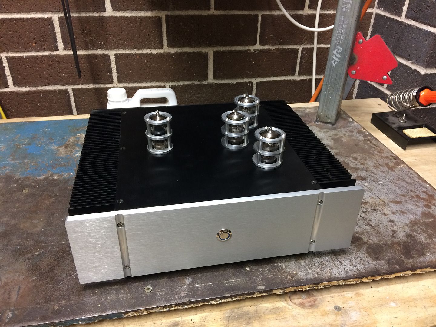
My M3 tap came in the mail today so I set to drilling holes in the lid and mounting the tube guards. A bit of a nervous time as I didn't want to bugger it up and whilst a couple were tight, in the end they all buttoned up perfectly. I was planning on polishing the guards but with the industrial look of the amp chassis and seeing them in situ I may leave them a little rough as they currently are.

Of course obligatory photos:

D1B2A868-7DEC-4906-B2F9-8ADFD9BD5B75_zpssas1g5tz.jpg


C29B95A4-1E77-48B3-BF53-51D302DFDD3A_zpsuwfmu82x.jpg


Of course I still need to remove some marker dots.

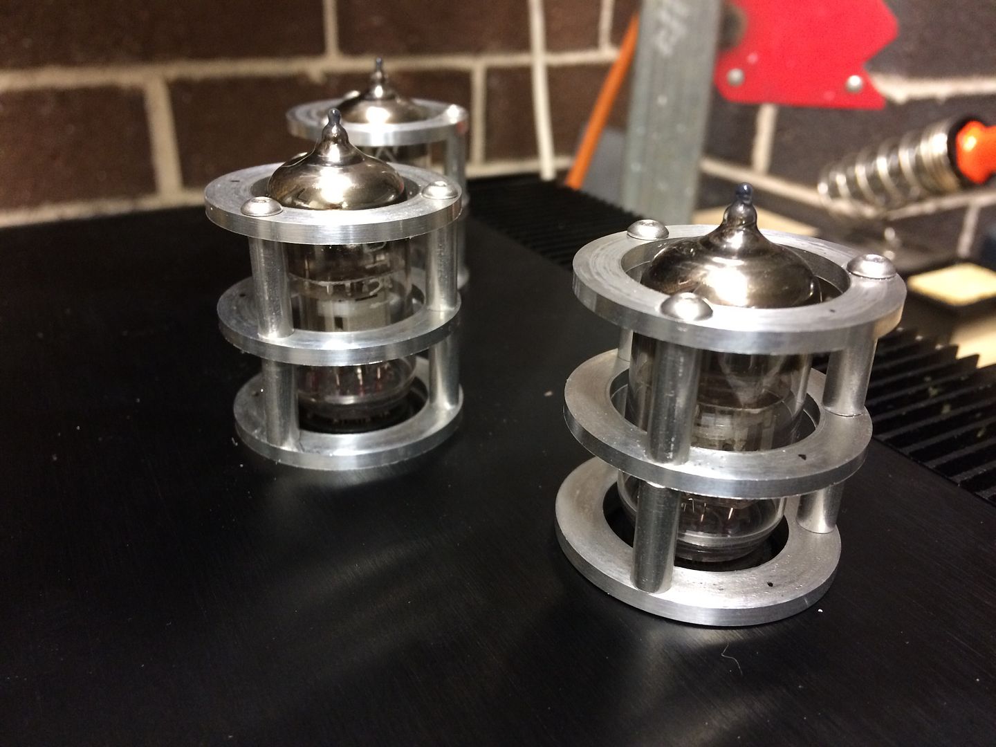
To say these are solid is an understatement, you can dangle the chassis from them, so they should protect the tubes perfectly, they also give the lid much better proportions.

I also swear they've reduced the hum by about 10% but the noise floor is still not where it needs to be and I'm not 100% sure where the issue is arising from, so I'm going to start again and use the spare PCB I have and start again (as it doesn't have the damaged trace), plus I will be increasing the Alu shielding a bit in the process too, in the hope it will improve things.
 
Last edited:
Hope it works for you and you find your expense and labor worth it in your cosmetic project. The LB T10 was raught with problems (engineering, design, and QC) problems from the start.
 
I'm pretty much finished now. There's hum at 12 on the amp but I'd probably blow the speakers at that level. Dialing up the gain on the amp has now meant its nice and quiet for vinyl listening and I get the sound.

Was it worth it?

Yeah sure. I had loads of fun doing it, plus I have a T10 that is unique. Financially there are probably better ways to go about it that might even yield much better sound too, but that wasn't the aim for me.
I could have spent less on my pre and phono but like you I had fun building it.
 
Yes, there's a much simpler way to illuminate the LED - just use the AC for the valve heaters. You just need a current limiting resistor (about 2k) and a diode in series with the LED to protect it from reverse voltage when the AC goes "the wrong way".

@rothwellaudio can I get your help with something? I did what you suggested above for my switch and it worked perfectly. 2k resistor and it lit up beautifully.

However it was blue and I wanted to change it out for a red ringed LED switch instead. Did that and no matter what resistor I out in there the ring iluminates so faintly it has to be pitch black to even see any light. Certainly not lit enough to see it's on.

Is there a difference with a Red LED im not aware of or is there a chance the polarity of the LED is backwards?

Thanks in advance.
 
Blue LEDs tend to be much brighter than red ones even if the specs suggest there's not much difference. Also, it's possible that the illuminated switch you're using has a resistor built in to it. Of course the diode in series with the LED has to be the right way round or the LED won't light up.
Anyway, to make the LED brighter you can use a lower value of resistor. You could go as low as about 300 ohms (assuming you're using the 6.3V heater supply).
 
I'm using the 15v heater supply and tried a bunch of different resistors and it still only barely glowed. It's currently in there with a wire (no resistor) hence why I thought I'd ask.m

I thought maybe I had the LED in the switch backwards or the diode in the wrong way as the switch has a slight glow but it's hard to see.

I'll get the multimeter on it and make sure I have both the right way and go from there.
 
Tonight I took to my modified T10 with the soldering iron again. This time I wanted to remove the earth switches from the signal path. It was an ill thought out solution and the cheap eBay switches were probably taking more away from the signal than they were helping to solve for.

Whilst I was in there I thought I would use some of the left over Van Damme Starquad I’d bought to upgrade my TT internal wiring, as I think it’s top quality stuff that makes a difference if you have crap wires, plus I used some eBay cable in there before and I’d rather replace it with a known quantity that I know performs exceptionally well.

I’m pretty quick at these things these days and I have to say the wiring looks a million times neater inside. Which is always a good sign.

I was very careful too so that I could pull some of the signal wires out midway along the cable to preserve the screen all the way down the wire.

Have to give it a run this evening (of course) and I’ve been blown away again. The treble has lost that harsh edge and blends much nicer in to the mix. Not only that but I swear the bass is taughter, crisper and deeper!

I said it in another thread but I’m amazed at how you can really limit the potential of your system with simple things like wire. The Van Damme isn’t even expensive!

I recommend it strongly.
 
Last edited:
Anyone have any suggestions for cable for my umbilical? I am currently running 240v 7A (which I think is complete overkill) wire in twisted bundles from the Preamp Chassis to the Chassis for the transformer. Its not long enough, not very flexible and I'd like to make sure its earthed back to the main chassis. I'd like an already made cable (8 core I will need, 220v x2, 0V, 6v x2, 15v x2 and an earth) if possible but worst case recommendations on standard wire so I can build my own. What amperage would the transformer wires generally see as a max so I can use that as the specs, as I mentioned I think the 7A is overkill and definitely contributing to the lack of flexibility. Also do I need to twist these wires if they are not near the preamp or should I do it anyway as they will go near signal wires from the TT and to the Amp (line level)?
 
There’s some noise on the preamp that I’m not happy with. I’m wondering if the use of Starquad has meant that the last part of unshielded audio signal wire is picking up some interference and so I’ve purchased some regular patch cable and will run if separately for the input and output and make the screen as long as possible right up to where the signal is terminated on the RCA to try and limit every chance of it picking up noise.

Will also grab some of the screen (from some cutoffs of cable) and protect the other audio signal as much as possible.

Other than the noise which is only heard at high volume, it’s sounding bloody brilliant! Cannot wait to get a better cart on it to test out its true potential.
 
I made my own from Van Damme Patch Pro. Floating ground at non source end.

I had cheap cables before from eBay (although they looked quality and thick) and it made a big difference m.
 
I’m abandoning the Starquad in the preamp as I’ve found it’s developed hum since the change. I suspect the problem isn’t the wires themselves but the fact that the 4 wires share 1 screen.

Where the wires terminate on the back in the RCA’s I’ve had to run the signal wires approx 40mm without any shield and this is pretty close to where the power switch wires terminate on the board too (the board runs in between the RCA’s).

As I was listening this evening I’ve actually found the hum is only in the left channel to audible levels at normal high volumes.

Either way I’ve bought some more patch cable from Van Damme and will look to run the input and output pairs of wires separately so that I can keep them well away from the board (and power switch wires).

I’d like to run screen on each signal wire as close to the return on each RCA. The patch cable shares a shield across 2 signal wires.

Is this ok to have a small run of unprotected signal wire?

I was thinking of cutting off some extra shield from the cable and looking to put that over one of the signal wires so they’re as protected as possible. Is that a good idea?

Does the return signal path through the screen actually offer any protection or is my hum from somewhere else?

Edit 2: is it worth using a run of patch cable each channel? That way I could use the 2 inner wires as the signal and return and also look to ground the shield at one (or should I do both) ends?

I have a meter of cable coming so no issues on whether I have enough.
 
Last edited:
I’m preparing myself for the latest incarnation of my preamp. With the main aim of getting rid of the hum. It’s not a big problem in the right channel but is an issue in the left. Reading up on the web I’ve found some good discussion on these 2 threads that I’ll use as my guide:

http://forums.stevehoffman.tv/threads/help-preamp-ground-loop-hum-how-to-fix.636504/

http://diyaudioprojects.com/Technical/Grounding-Shielding/

Essentially I’ll be replacing the cable for the inputs/outputs with much better shielded cable and use a floating ground at each source end. Then I’ll be following the second link and trying to make sure my 3 grounds are done properly vs the current way I have it setup.

Cable is on the way from the UK so as soon as that arrives I’ll be digging in (again).

It’s become even more critical to get it silent now because I have a new cartridge (Ortofon 2M Bronze) which is a little quieter than the Red and therefore highlights the hum more.
 
Did the 10 come with a switch to disconnect the earth ground on the power cord? The small amout of hum I get with the 11 became even less after flipping the ground switch disconnecting the earth ground. I thought the switch was a nice feature in case of a ground loop problem. Floating grounds have been hit and miss so far for me. It depends on the circuit I guess. Good luck!
 
Yea it does however I’ve found so far it makes zero difference which makes me question if my problem is ground hum related or maybe induced noise in signal paths.

My T10 is far from standard too, so I need to chase the problems I’ve introduced too.
 
I'll be watching! If you find the answer, maybe your fix will work to kill that bit of hum I have at full volume. :biggrin:
 
I need to read those articles a few more times so I can try and get it right in my head. Sounds simple until you need to put it in to practice.
 
I’ve found the source of my left channel hum. I still need to work on the background hum level but I have the new wires and some other ideas for that, but at least now I don’t have an annoying hum in the left at reasonable listening levels. What was it?

The external transformer chassis appears to be affecting something. I moved it and the hum in the left changed. Now I need to find a place to hide the chassis where it doesn’t have any effect on the audio.
 
Back
Top Bottom