I was a but worried that I had measured correctly and in the end came very close to having to file off some of the bottom of the plate. It fits but just barely. I used 3mm thick aluminum because I wanted it to be thick enough to drill and tap M-3 holes for the mounting screws. That worked but if I was to make another one I would make the plate 1mm shorter, it just barely passes above the main PCB.
The power switch boot in the M-70 is also cream colored. I'm guessing that the light bulb is also just yellow enough that when combined one ends up with the yellow power light.
View attachment 1162666 View attachment 1162667 View attachment 1162668
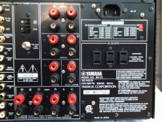
I mounted the speaker-A posts with the holes vertical but installed the B posts with the holes angled out at about 45° to make it a bit easier to get wires into them. That means making darn sure that the wires aren't too long, but that's always the case anyway.
Notice that the clear plastic bases aren't clear any longer. More on that in the next post.
Cheers,
James
James,
I've very much enjoyed following your meticulous, detailed, and thorough work and progress. However, I have to say your binding post alignment bugs the crap out of my OCD.
")
If it were me, I'd angle them all at 45*. Just saying...
Cheers!
 . Those little allen heads bolts look very neat also. Good call on turning the clear bases down to allow pass through on the rear panel.