Need advice - Optonica SA - 5605 left channel distortion

Krosya

Well-Known Member
Hi,
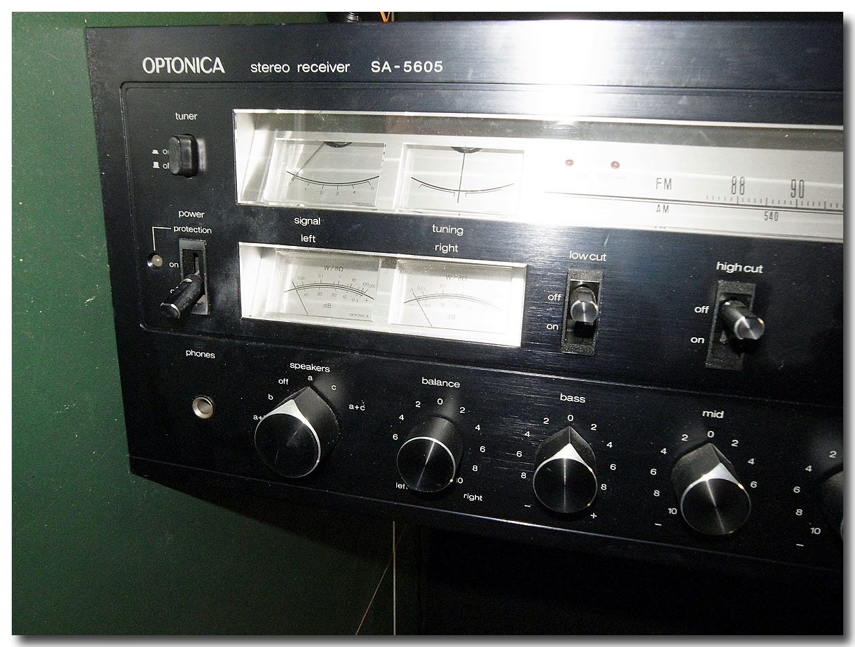
I'm hoping someone can point me in a right direction here. My Optonica SA - 2605 developed a distortion in a left channel. I almost cant hear at lower volumes, but starting about 1/3 up the volume dial and higher it becomes pretty obvious. Right channel is clean and clear. It's there with ANY source - tuner, tape, Aux, phono. I cannot hear it via the Headphones, just speakers. Tested with several different speakers, same result. All switches and button and dials were treated with the DeOxit, and I dont notice any other issues.
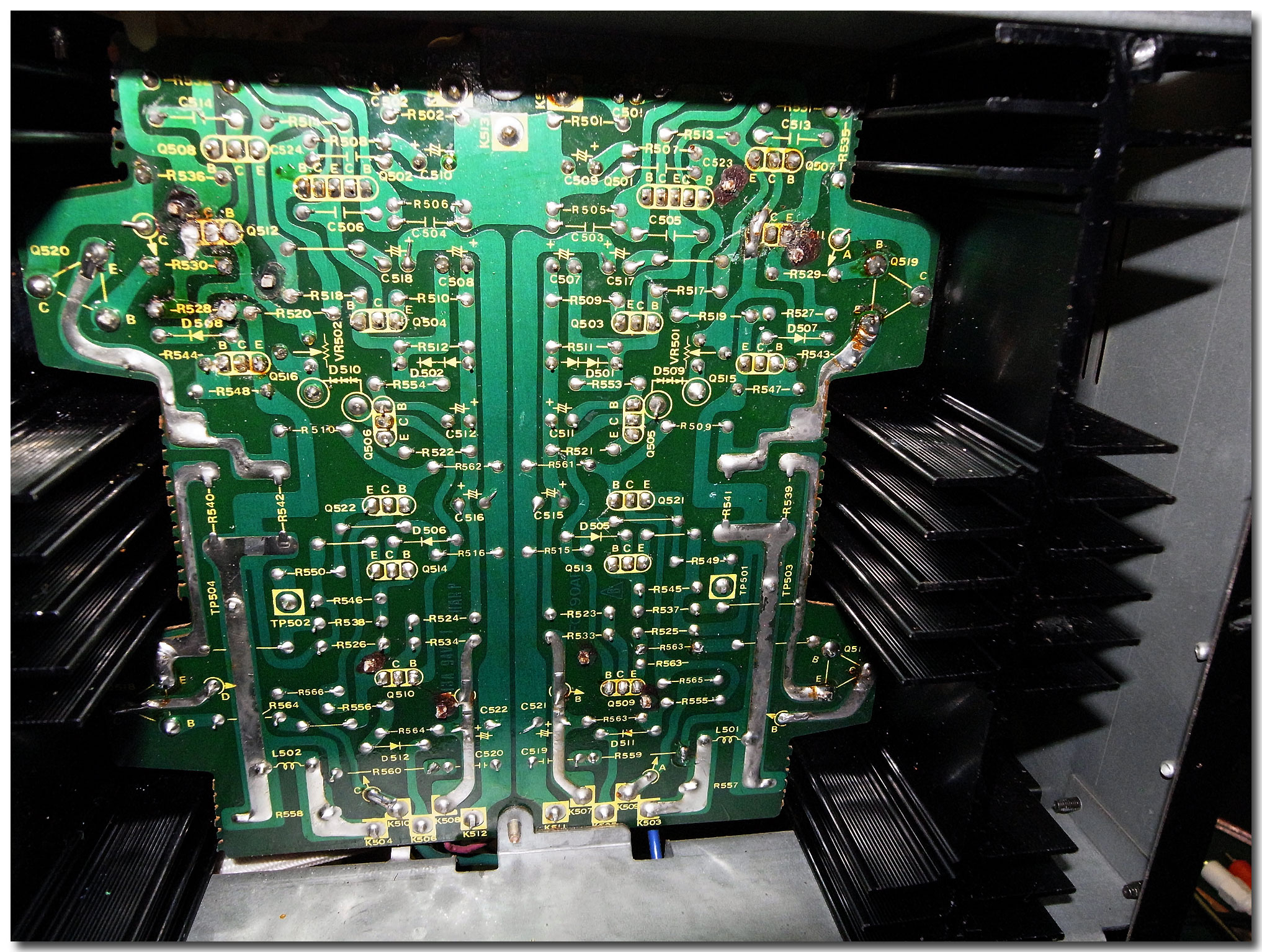
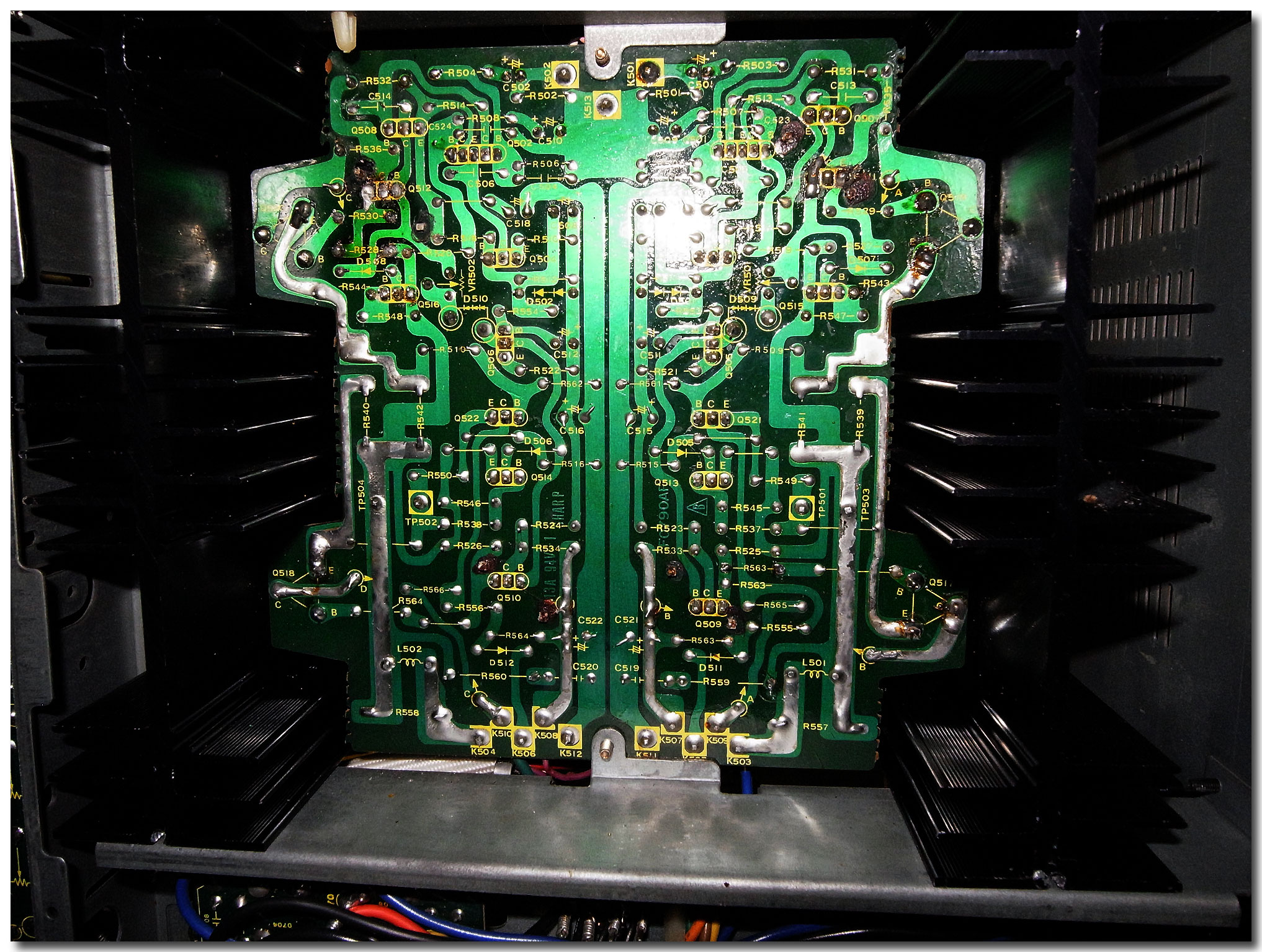
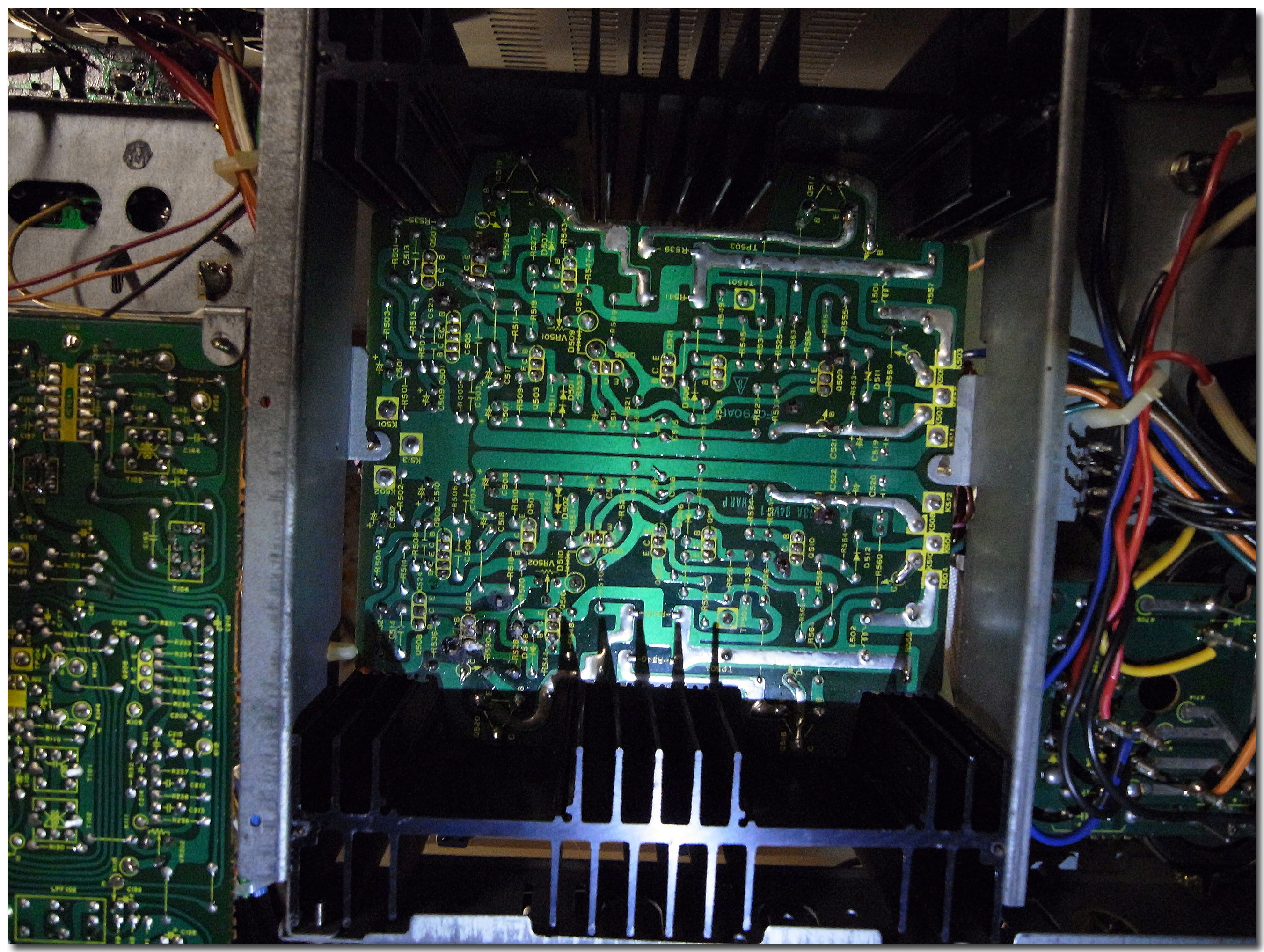
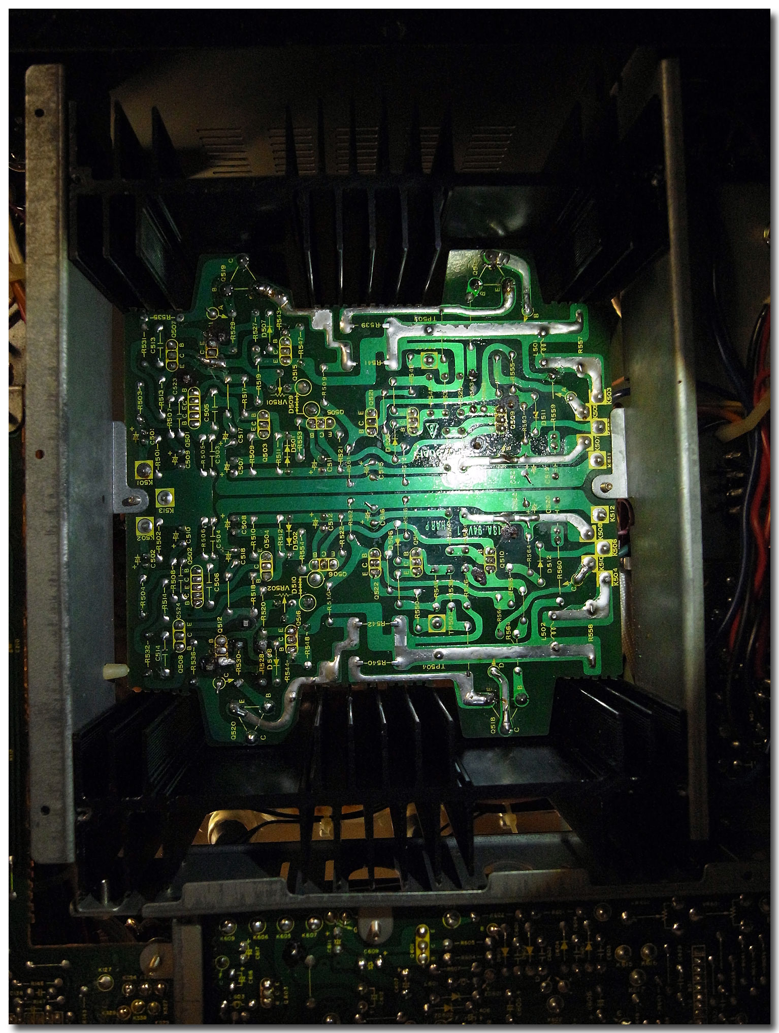
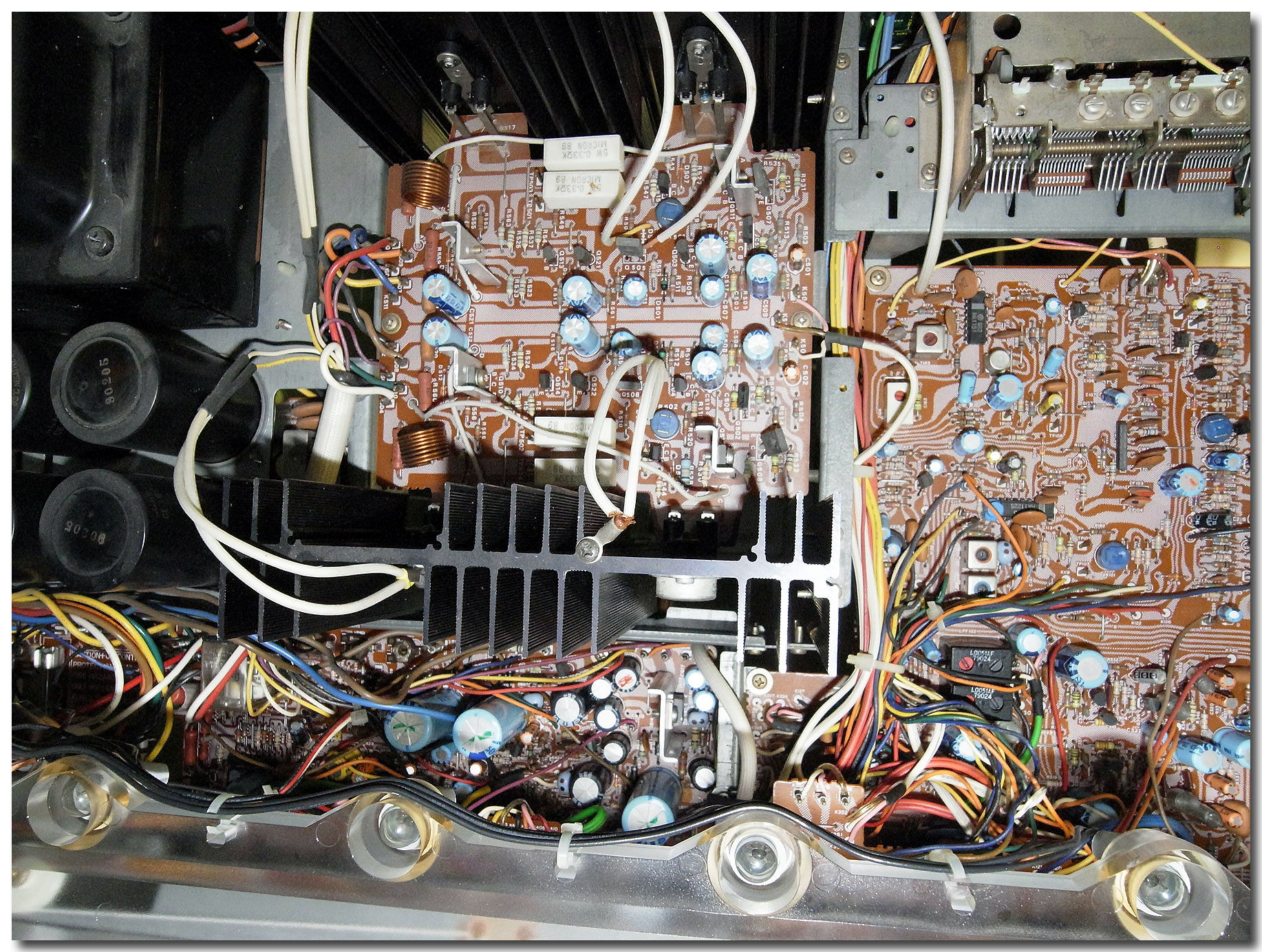
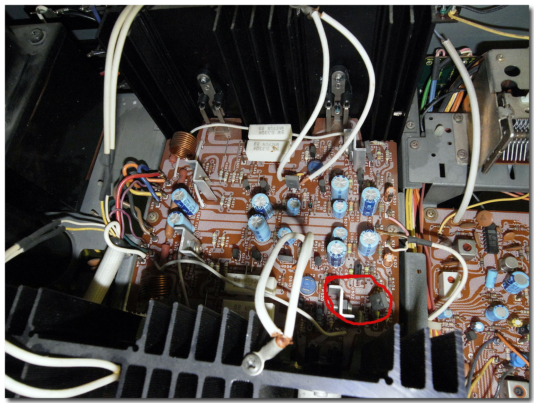
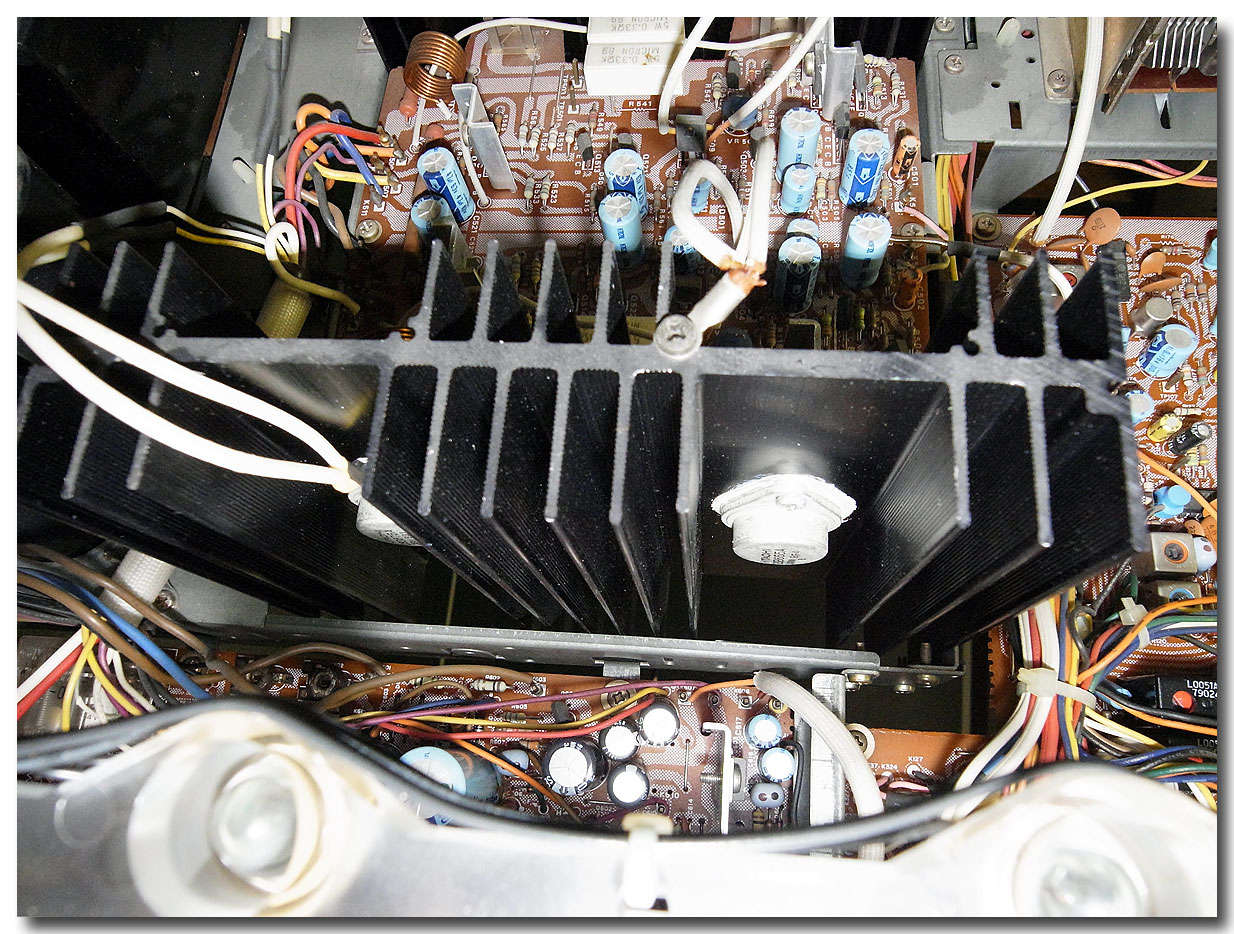
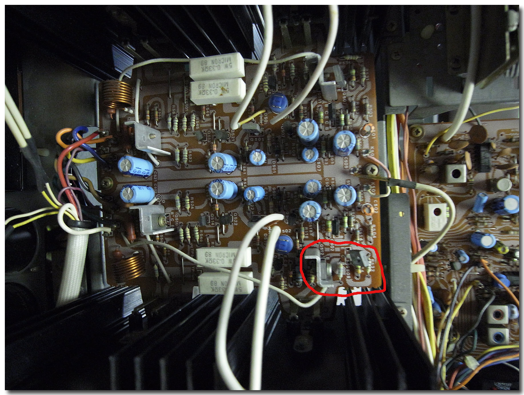
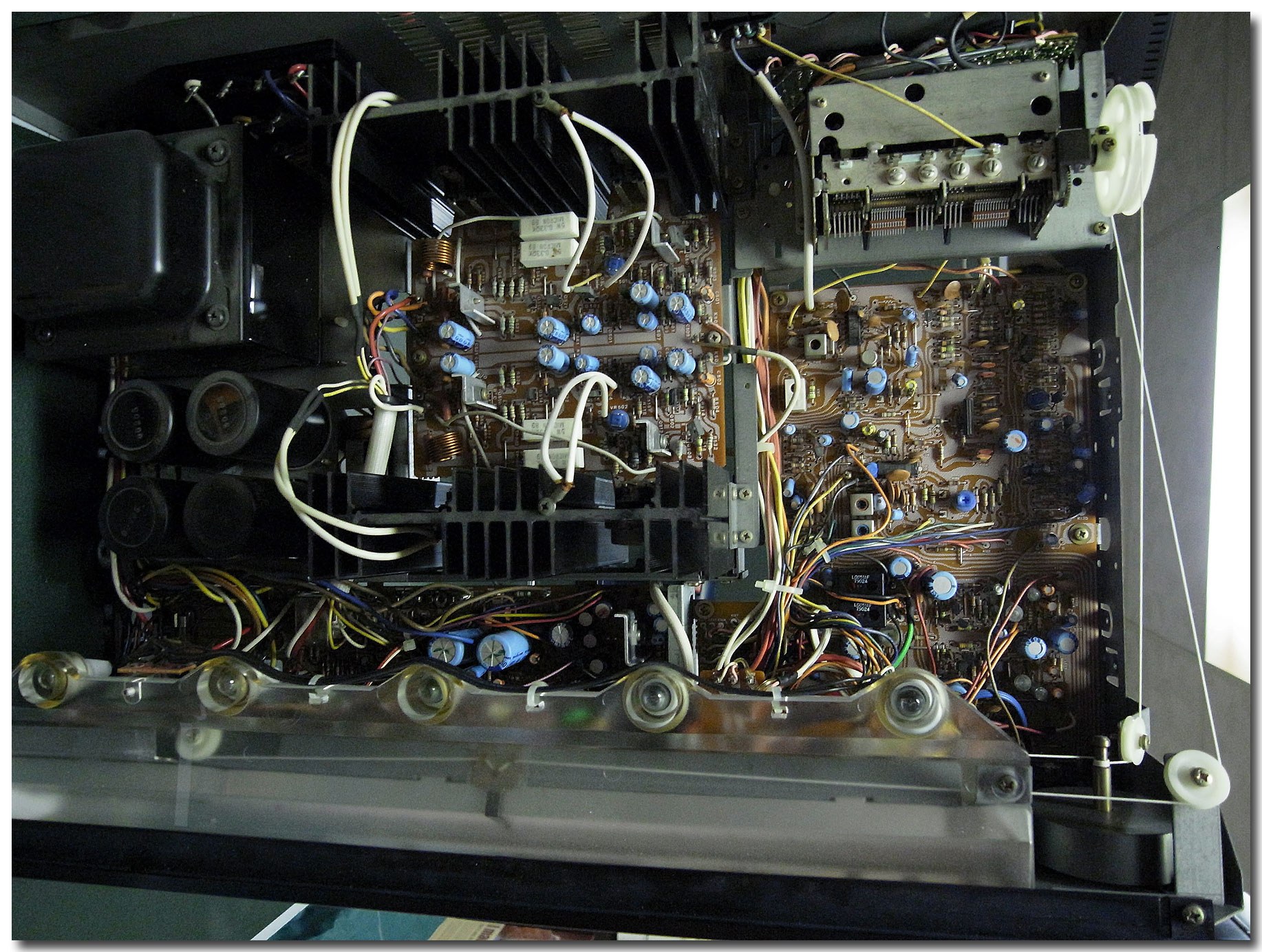
I took the top cover off and one thing I noticed - is that 2 transistors? (I think thats what they are) - I have them circled in a photos below are getting much hotter than any others on a board.
While I'm pretty good with the mechanical stuff, and can do some basic soldering, I dont know much about the electronics, so please explain things to me in a way so I can understand - like to a 3 year old. ;)
Hope someone can help me out . If you need more info - please let me know.
R0010948.jpg

R0010947.jpg

R0010946.jpg

R0010945.jpg

R0010944.jpg

R0010943.jpg


Thank you in advance
 
I don't have the schematic/service manual for that receiver, but it seems to be similar to other sharps in the same model range.

Look to see if there are any 2SC458 transisors on the amplifier board. If there are replace them as they are always causing issues.
Also it looks like there are a lot of fusable resistors on the amplifier board. The type that look like r513 and R523. Usually they are values like 4.7 ohms, 10 ohms, 100 ohms, 150 ohms etc. They go bad and either open, or increase drastically in value. Ohm all of the out to see if they are good. You can usually measure them in circuit, but if needed, you can lift 1 leg. Distortion can also be caused by an open output transistor or an open emitter resistor (the big white ones, but if they were bad the distortion would be apparent even at the lower volume.

The contacts in the speaker protect relay could be dirty as well, but that usually causes a distortion and low volume issue at your lower volumes, and usually clears up when you crank it.
 
Last edited:
There is a Service Manual for its big brother on hifiengine which may help a little. They’re not the same, so take the following with a grain of salt. In comparing your photos to the SM, I only notice one set of trimmers on yours. These should be for setting the bias for the left and right channels outputs. The SM for the 5606 shows a second set for setting the DC offset.

Here's what I'd suggest for starters:

Build a Dim Bulb Tester. It may just save you from the receiver becoming a doorstop!

Once this is built, try powering up the receiver through it to see if you have a dim bulb or one that glows brightly or has a pulsating bright/dim cycle. If a bright light, with say a 100-150W incandescent bulb, you have an over current situation and possibly a blown output or other short somewhere. If this is the case, do not do the following in the order presented here because we'll need to change the order of things and you'll only power up on the dim bulb til things are sorted out.

Remove the bottom cover and carefully inspect the solder joints around the area of the hot transistors. Check for ring cracks, loose joints, etc. preventatively reflow these regardless of what you find.

I've circled a couple things on your photo.

Blue circles are the 2SA798 5-legged transistors. These are the differential inputs and usually will have to deal with the balance of power (load sharing) of the outputs (also known as DC Offset). On your 5605, you can’t adjust the offset, no trimmer, but I'd do a comparison between the clear R channel and the distorted L channel to potentially give you some clues as to what's going on. Set the selector to AUX, min Volume, Tape Monitors to SOURCE. Meter probes in the speaker jacks according to polarity., meter set to DC if auto ranging, if not, set to a low voltage setting where you can measure millivolts (mV). Should read close to 0mV. Anything below 50mV is decent. If you're getting a much higher reading, the 2SA798 may need changing.

Green circles are test points and the associated trimmer for your bias setting. 5606 SM calls for 10mV, again on the DC volts setting of your meter, so this should be about right for your model also. It did not state which probe should be attached to which test point. Probes with mini grabbers work best. If you don't have these and just have alligator clips, I'd solder insulated extension wires onto the TPs and clip the leads to those. DO NOT ALLOW THE PROBES TO TOUCH EACH OTHER UNDER POWER, YOU'LL SHORT THE OUTPUTS. Same switch settings on the receiver as for checking the DC Offset.

Check the good R channel first. Then the distorted L channel. If the L channel is higher than the R channel, adjust its associated trimmer counterclockwise til you read 10mV. (You can do the same for the R channel, but I'd suggest at first just checking it since you're trying to diagnose the bad channel by comparing it to the good).

Yellow circles are the varistors. These aid in adjusting the bias as the outputs heat up, which is why they are attached to the heat sink. If one of the wire leads is broken (they are usually very fragile things), this could be causing the issue as the outputs are getting overheated as you turn up the volume (i.e. it's not doing its job and keeping things biased correctly).

0333F373-E279-4B01-A82B-26DE5A12A336.jpeg

EDIT: There's also two diodes on your board D501, 502. They are green and black. The 5606 SM lists them as HV-46GR and shows a “double diode” symbol for them. IF they are anything like the VD-1212 double diodes, they could be problematic. I couldn’t find out much about them online, but the supposed NTE equivalent (NTE177) only shows a single diode, so don't think it truly is an equivalent. The HV should have a voltage reading of roughly 1.2V. If they are bad, you should be able to replace them with a pair of series connected 1N4148s.
 
Last edited:
Thank you so much guys! I will get right on checking into all this and post my findings. I did check DC offset and on both channels it was low - Left was 1.8 mV and Right 2.3mV.
Looking at the varistors - I dont see any obvious breaks/cracks.
From doing some research - I was wondering if I should look into the output transistors?
I will have to double check, but I think 2SC458 transisors are not present on the board in the center (Amp. board?), but there are a few on the board on the right - if you look at my pic that shows the whole receiver, right below the tuner thingy? Should those be replaced as possible cause of the problem?
Thanks again!
 
BTW, Am I right to understand that Left channel is the part of the board that is toward the back of the receiver and Right - toward the front?
Looked at the back of the board - do not see obvious breaks, cracks, etc in the connections. But keep in mind I have very little to none experience with this stuff, so I may overlook something.
 
Checked bias settings. One on the closest to back was 13 and I adjusted to 10, one closer to front of the receiver was 2 and couldn't adjust beyond 6mV. What does this mean? Output transistors are bad? Something else?
 
Did you check for bad solder joints under those hot transistors (which are most likely the drivers)? If they aren't conducting, you won't be able to set the bias. I'd do this before removing outputs to check. Reflow that section.

re: 2SC458s, looks like you may have several on the amp boards The ones circled in teal, look like an outhouse. Confirm they are or are not C458.

The fusistors mentioned by Tom are circled in yellow. Some look a little sketch from the photo on the side of the board that has your red circle. You can do a side by side comparison with the unit unplugged to get a rough idea if they're out of spec. Measure one on the R channel and compare the same one on the L. As long as they are close together in measurement, they're probably OK. Compare them to what the banding says they should be.

The magenta circles are the HV-46s. To measure you'll have to lift at least one leg off the board.

I drew a dashed orange line to delineate the channels. Looks to be mirror image, so that should help since there's no SM.e1_optonica5605.jpg
 
Thank you for your input. I will look into all this - will not have much time till the next weekend to spend on this, but as soon as I do - I will post what I found out. Hope together we can get this thing working properly again. Thank you very much!
 
No worries...that's what we're here for. Do look up the Dim Bulb Tester and make one if you can before doing too much work on this though.
 
Ok, I was able to look and check some things - none of those "outhouses are C458.
Checked all the resistors - found a couple that dont seem to work - R526, which looks like 100Ohm, 5% and one R530 - 4.7Ohm, 5%. Not sure what watts they are. So, how can I buy new ones with just the info I have? BTW, Where to buy them from?
Also, since board is mirror image, I was looking at the R528 on a Left channel - its larger and blue, comared to it's counter part in a Right channel (527). Wonder if someone replaced the original before ? I suppose I need to put original, just like in a Right channel in its place? Not sure if you can see this in a pictures - its slightly (second after the 530) to the left of my red circle.
Thanks again, John, for all your help.
 
Were they checked “in circuit” or did you desolder them to test? If they tested bad or wonky in circuit, next step will be to desolder at least one leg and pull it out of the circuit to ensure an accurate reading. If still bad, here's where the educated guess starts to occur, since we don't have the exact service manual.

Looking at the 5606 SM, resistors in and around the drivers in those values are listed as “1/4W 5% Fusible” along with the value in ohms. There are a couple other fusible resistors mentioned in 1/2W (1ohm and 10ohm), and then some larger metal oxide resistors in the 1-3W range.

Your safest bet for replacements here will be 1/4W Metal Film resistors that are “flameproof” (which I think all MFs are). The worst that would happen is it would open up sooner than a 1/2W resistor would if the 1/2W was spec'd.

These would be a good start:

https://www2.mouser.com/ProductDetail/KOA-Speer/MF1-4DCT52R1000F?qs=sGAEpiMZZMsPqMdJzcrNwsDBSEuVlBlrLsBT2w23I6E=

Yageo brand are also fine. I'd buy in quantities of at least 10each to get the discount, but you may decide on more if you want to replace them on both channels as preventative. To save on shipping costs, download that 5606 SM and do some comparing between what you actually see and what the other unit calls for in various spots

i.e. are the output emitter resistors the same? Drivers the same transistor? Resistors attached to the drivers the same? Look at the power supply section...what capacitors are needed for a rebuild? Will it be a full unit rebuild or are you just trying to get it running? If a full rebuild, you'll need to start making a list of the caps in each spot as installed (value/voltage), as many companies made running changes that aren’t documented in SMs, and you don't have one anyway. Definitely lots of photos showing cap orientation as sometimes boards have misprints as to polarity.

If the latter, at a minimum you should plan on replacing power supply capacitors (the large filter caps may be fine) with 105 C rated low-ESR types like Nichicon HE, PW, PM or Panasonic FR, FM, FC, check and regrease output and other heat-sinked transistors, and possibly the rectifier diodes.
 
Let me start by saying that I am really very new at this, so most of the terms and things you are talking about are not very clear to me. I will answer best I can.
First, since I'm not very skilled at this - I do not plan to do a full restore - just want to fix the distortion. Receiver sounds good to me otherwise, so I dont want to get too deep, as I make cause more damage than good. I did download the service manual for that similar model, but most of it is beyond my understanding, so I really appreciate if you "hold my hand" walking through this.
I did test things in circuit. I dont want to de-solder things if I dont have to. So, I can buy those resistors that you advised, and try to install them and see what happens? Would this be a good move?
I am not sure I understand everything you said in the last 3 paragraphs in your last post. If I get it right - looking at the board - all components look the same in Left and right channels, other than that one large blue resistor I pointed out in my previous post. Things look pretty much mirror imaged and while I didnt check every one - overall it appears that both channels are the same.
So, based on this, what do you think my next step should be? What about the power(output) transistors? Are they a suspect? Should I replace those resistors first and see what that did?
Thanks!
 
OK...not a full rebuild. That helps us decide how to proceed. Let me think through some things before you get too deep.

At a minimum, you will need to desolder some things to check them before you should think about placing an order. No sense ordering resistors right away to then find out that the transistors are bad and have to place another order.

Oh, one other thing before we go further...

What tools/equipment DO you have? At a minimum you'll need:

Pencil type solder iron (25-40W)
Desoldering braid
Solder (60/40 blend or thereabouts is fine but don't go for lead-free)
Multi-Meter (which I assume you have since you've tested some things)
 
Last edited:
Have all things you listed, other than disoldering braid, but I can get that, I suppose some local place should have that. And that's all the tools I have, as far as electronics go.
 
You can get the braid when you order whatever parts will be needed. Mouser or digikey are my go-to places for parts for repairs.
 
I don't have experience with the particular brand of desolder pump you linked, but yes, that and the braid are fine. You'll need them to get at the parts to do some testing.

Do you have a local store (Radio Shack, etc) that has electronics components? If not, it is in your best interest to do a little grunt work in checking things before placing a parts order. By gruntwork, I mean:

Make a list of the different Transistors installed on your board (that will help us determine their function and potential reason for the distortion) i.e. Q507,508 2Sxxxx to include any letters after the numbers. They may only have the ABC or D followed by the number (2S being assumed).

Same thing for the electrolytic capacitors (I count 14). uF/Voltage

Take a good detailed shot of the trace-side of the board. You stated you looked at it and it seemed fine, but you've also acknowledged a lack of experience.

Once you get your desoldering stuff you'll need to check those resistors you got bad readings from by removing one leg to get it out of circuit

You should also check:
D502 ... the green and black diode
The varistor attached to the heat sink. Just because it "looks" ok doesn't mean it is OK
Most likely you'll need to check the other transistors (at least the ones on heatsinks, but without knowing what you have, it's hard to say for certain which ones are culprits)
You can pull and check the output transistors since they're socketed and don't need to be desoldered right now.

Here's a good guide on how to test transistors and diodes with a multimeter if you're not sure.

Wish there was a service manual as it would help ALOT, so you get to be the eyes on this...
 
Ordered braid and pump, should have them soon.
No Radio Shacks around anymore, but I do have Parts Express about 40 min away from me. Maybe some others, but not sure.
List of Transistors (all but those that are attached to heat sinks - cant see what they are, unless I detach them from the heat sink - one of the on the bottom right that I had circled in my pics before is the one that gets hot):
I made a list of the ones for the Left (bad) channel since ones for the Right channel are the same - this goes for all the other parts, caps, etc.
C1213A
B646 8H3
B648B
A673A
A798 86G - one with 5 legs
D668A

Caps (left channel only)
47mV63V
47mV63V
47mV16V
47mV16V
47mv63V
220mV16V
3.3mV25V - little orange one

Output transistors for left channel - left side - 2SD675A
right side 2SB655A - same for the Right channel.
Varistors - not sure how to check them - I gently pulled on them - seem to be attached. What else should I do to check them?

Here are some pics of the board from the other side - let me know if you need more detailed ones of some areas:

Left channel is on the left:

R0010967.jpg


R0010955.jpg


Left channel is on the bottom:
R0010957.jpg

R0010963.jpg

R0010969.jpg


It looks pretty clean to me for the most part, but looks like it was worked on at some point.

Hope this helps - let me know what I should do next. I may not be able to do much until saturday, but I try to find time whenever I can to work on this. Thanks again - I really appreciate your help with this.
Best!
 
Good to know about PE fairly close...you should be able to at least get some resistors and diodes if needed. Not necessarily where I'd go for any needed transistors.

Will need to know what the board numbers associated with the transistors are to try and see similarities to the other unit's service manual if possible (i.e. Q502 - A798). Several of the transistor types match, but want to see exact location used for the comparison. You will need to desolder the suspect warm ones to test them when you get the braid, so we can get the numbers off them then.

Thx for the pics of the trace side. I’ve marked up one for some suspicious solder joints, though I'm working from an iPad right now and couldn’t zoom too well. Use a good strong light and magnifying glass to look at them. You may need to clean some of the flux off the board to get a really good look. Acetone or 91% Isopropyl alcohol with an old toothbrush to give a light scrub works wonders. Put some paper towels at the bottom of the board (receiver standing on its side so the board is vertical) to catch the runoff.

Another way to check some of these is to lightly wiggle the part while looking at the solder connections. Regardless of the above, there are also some large blobs of solder which could actually be a cold joint and not making contact.

Did you get a chance to look at the linked diode testing for transistors? If not, give that a look see while waiting for the desolder stuff to arrive. Pull the outputs from the left channel and test them one at a time, reinserting each back into the circuit so they don’t get placed in the wrong side.? In short, your DMM should show a reading of roughly 0.55V on two of the 6 combinations of meter probe settings. All the rest should read 0L. The two good readings shouldn't EXACTLY match, if they do, there could be an internal short. Likewise, they shouldn’t read very low, like 0.2V.

Post #11 of that thread shows what your looking for. Shorthand will look something like this:

D675A
b,c - xxx
b,e - xxx
c,b - xxx
e,b - xxx
c,e - xxx
e,c - xxx

As to the varistor, you'll electrically check it with your meter after you get the desoldering stuff.
EDDD12D3-B209-4FEC-8EBF-411DD99CE3A2.jpeg
 
Last edited:
Back
Top Bottom