Kenwood KR-9600 My next big project

patra710

Active Member
I have been working on vintage stereos for about a year now. I have mostly work on Pioneers, this is my first Kenwood. And what a monster I pick for my first one. This stereo did work when I first got it but one side was running warmer then the other side so I put it on the shelf until I had a little more experience. I do have a service manual for it and I'm starting to search the forums here for information. The one question that I have for starter is what size light bulb would I use in my DBT for this over size monster?

kenwood kr9600 pics-1 002.JPG
 
Thanks gort69, could I use a flood light. It hard to find light bulbs anymore at that wattage.
 
It is tough to find them in the old standard frosted white, but a decent hardware store should have a 150W in the decorative bulb section - it'll probably be clear. I just bought one last month.

I'd assume a flood light or a spot light light would be fine if it's a standard filament incandescent - I wouldn't know about halogen

Curious to know what your plans are for the 9600 - I got a lot of good help here going through a couple of them recently.

Here's a great reference: http://www.audiokarma.org/forums/index.php?threads/kr-9600-restoration-info.441957/
 
In place of a 150w bulb you could parallel a couple 75 watt. I use those light socket pig tails that they use for temporary lighting.
 
Thanks guys, I will look harder for a bulb or parallel a couple.
This is one stereo that I am going to keep. The others that I work on I have sold. I'm retired now and this is what I want to do. I still need to build my bench up more. My dummy loads are only 100 watts and there are a few other thing that I would like to have. My rebuilds have been successful because of this forum.
My mains line voltage here is 120 volts and that what the back of the stereo ask for.
The only thing that I am worried about is the IC output transistor. I am not going to plug it in again until I got the DBT ready for it. And I still have a lot of reading to do before I start.
 
Thanks guys, I will look harder for a bulb or parallel a couple..
Just to be clear if putting two 75watts together in place of a single 150 make sure you put the two paralleled bulbs in series, otherwise it will simply light the bulbs but won't be of any protection. IOW series parallel it. You want all the electricity to the amp to flow through the filaments of the bulbs.
 
I restored mine a number of years back - they really are exceptional.
One upgrade I highly recommend is to upgrade the opamp in the tuner's audio section - major improvement!
 
I found a 150 watt light bulb and got the parts in that I ordered for this stereo. When powered on I had no lights and no relay click. I found a blown fuse for the 7 V AC line and a dead short on pin 9 on the power supply board. I traced the short to the selector switch which works the function lights. All I did was wiggle the wire leading the the selector switch and my short was gone. Why I need to find out. But now I have lights and a relay click. Moving on to the next step.
 
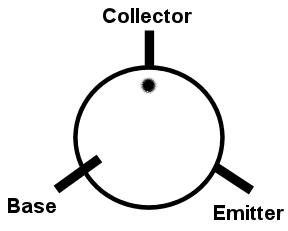
I'm replacing the transistors on the amp board and just want to see if my way of thinking is right. The pic below is of the silkscreen on the amp board. The way that I see it is that the white dot is the collector, the white line that starts at the edge of the circle and goes out is the emitter and the white line that goes through the circle is the base. kenwood kr9600-4 018.JPG
 
Here 'tis:

Transistor_Notation_9600_Style_zps1o1cj6kh.png


When the PC board holes are lined up in a row, it's hard to read. If there's any doubt, check the schematic and compare to the foil layout to make sure, but consider that 95% or more of all Japanese transistors have the middle lead as a collector....but don't assume - check it if there's any question.
 
Thanks EchoWars. the ztx694b is CBE, I got them in with a little twisting and a little heat shrink tube on one of the leads.
 
Question, on the power amp board there are two 3.3uf 100 volt E-caps going from the negative and positive inputs of the big filter caps to ground. I was wondering why they are there.
 
Just local filtering for the unregulated supply. The value isn't critical, but the idea is to provide a local path to ground for any noise picked up in the wiring between the caps and the PC board.
 
Good luck with your KR-9600. I gave my a good going-over and found several leaking electolytic caps on the Power Supply and Relay boards underneath the unit. I ended up replacing all the electrolytic caps on both boards. All else looked good. By the way, one side of the unit (the right side looking from the front) will run warmer that the other because the power supply pass transistors are located on the right top side with fair sized heat sinks (unless you meant that the one side of the final amp heat sinks were warmer than the other).
 
Thanks Dave. If I remember right I think the right heat sink was running warmer then the left. I rebuilt the power supply, relay and regulator boards and I'm now working on the power amp boards. This stereo did play music before so I am sure that it will again. The only thing that I worry about is the output IC's.
 
On the power amp board I was going to replace the two tantalum caps, C2 & C13, with one film cap as others said they have done. Looking at the schematic, it shows these two tantalum caps in series with nothing in between them. But the foil view and the board itself has R2 between them. If I install the film cap it will take R2 out of the circuit. Am I looking at this right. I think I am going to replace the two tantalum caps with E-caps.
 
after a second and closer look, I was wrong. R2, C13 and C2 are all in series. The silk screen and foil view both have a line going to far. So I will go with the film caps.
 
Back
Top Bottom