10,000uf 63v audio cap needed

I would like to find the ratings on that Elko. The Rubycon could also work if I can determine it has 22.5mm spacing. I also found this United Chemi-Con SMH (below) I'd really like to use. It is perfectly spaced, 80v and could also offer a little more headroom. It has 6amp ripple vs. the 4amp for the 63V with comparably low ESR. Does anyone have experience with this vendor? It is based out of Honk Kong and most of the website is in French. Not sure if this is a sketchy vendor or not.. Anyone care to weigh-in?

http://fr.heisener.com/ProductDetail/United-Chemi-Con/ESMH800VND103MA50T
 
I have some Panasonic 10000µF 80v left here. http://www.mouser.de/Search/Product...virtualkey66720000virtualkey667-ECE-T1KA103FA I think they will fit the layout, but they are 40mm in diameter. It' funny, because i bought them to recap my E-202 but it needs 10mm to fit without modification. Where do you live?
Thank you! It looks like I am locked in to the 35mm diameter. It is the only other spec that is really limiting me besides the 22.5mm lead spacing..
 
For those that have soldered wire leads on the snap in type capacitors, how did you fasten the cap to the circuit board.

I am researching this issue and have gotten conflicting opinions.

http://audiokarma.org/forums/index....citors-cant-find-online.762676/#post-10417045

Pictures might help me.

Thanks!

http://audiokarma.org/forums/index.php?threads/ax-500-thread.749463/#post-10168013
http://www.audiokarma.org/forums/index.php?threads/ax-700.645067/page-9#post-10265110

Cheers,
James
 
I would've loved to get my grubby little hands on these cool looking Audio Note Kaisei (BlackGate successors), but they aren't offered with the correct ratings and lead spacing. :dunno:

audio-note-kaisei-all-350.jpg
 
Thanks everyone. I ended up using the 100V United Chemi-Con SMH series with the VND termination type because they ended up being a direct replacement for my original 63V UCC caps with the exact same pinout. It was VERY hard and took a very long time to finally get to the point where I had a good part # that would just drop in. The replacement I used is # ESMH101VND103MA63T for anyone else needing a similar quality cap for another project. They look like very nice and have a good feel and weight to them.

I was surprised to see a flash when desoldering each of the two, old capacitors! is this normal? I was extra careful on removing the second old cap (knowing that it also might cause a flash) but it Still caused a spark as well. It was the 'jumper wires' next to each power cap that took the brunt of it. I did a quick visual check of all the glass fuses inside and all appeared ok. Hopefully, it appears it was designed this way? Otherwise I am totally screwed after spending hours and hours on this project. I plugged it in and turned it on. Everything lights up and appears normal so far..

The full recap is now complete. I believe there was 71 electrolytics inside, including the power caps. Hopefully, when I get it all buttoned up and put back together it'll sound like a dream after the Silmics in the signal path get a chance to burn in a little. I used Oscons as decoupling capacitors on several of the many chips. Power section was a mixture of UCC, Kemets, Wurth, Panasonic FM. A couple others used in various places were Nichicon Cerafine, KZ and (my favorite) the pretty green Muse ES. It was a fun project to try and hand select each cap based on its function within the various boards and different sections. Look forward to the hearing the sound I was trying to generate with all the different caps installed.


SMH3.jpg


SMH.jpg


SMH2.jpg


caps.jpg
 
Last edited:
They look nice! :thumbsup:

Those big caps should be discharged with a 10K ohm resistor before you touch them with an iron. They can hold a charge for a long time.

You should also do the same thing with big new caps because they can make a small charge just sitting there kinda like a battery. I won't bore with the long drawn out technical details but it's true. :p
Everything is already soldered in place and installed. The new caps made no spark whatsoever, only the old ones. Do you think everything is probably ok then? I don't care about the old ones, so long as they didn't take anything else out with them when they sparked upon removal. It was at least 2-3 days since I had plugged it in and had inadvertently charged those old caps! I thought that had been enough time to allow them to dissipate their energy- apparently I was wrong. Hopefully the jumper wires in the circuit were put there to prevent damage to other components in such an event.
 
I think it probably just jumped onto the soldering iron. I believe the outside of the iron may be grounded or neutral to prevent people from getting shocked by a hot iron.

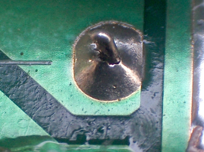
Don't take this the wrong way but I think you may have some cold solder joints on those big caps. :eek:

The photo makes it look like the solder is not wicking up onto the leads like it should. This will work for now but it will cause trouble down the road.

You have a better view than we do and I know sometimes the camera can play tricks with PCBs. It would be best to remedy it before you button the unit back up. :thumbsup:
 
The jumper wire connection on the pcb itself for each cap is actually scorched and brown looking around its little bare wire through-hole jumper connection.

I am just curious, why does it look like there may be cold joints? I think the solder joints look pretty good. I know the one on the bottom right doesn't look great in the photo because of the lighting but looks better in person. I used a fair amount of solder for each joint, more than what they had originally. If it looks like there's too much solder at the joint itself it's because they had sucked up a lot of solder already and I wanted to make sure they were even more secure than how they were originally. I used Cardas Quad eutectic solder because of its instant, low melting point and had the iron turned up to 720 degrees because the terminals are thicker than normal and I also had to heat up that copper bar enough to melt solder through its mounting hole. Everyone has a different approach to soldering. Mine is to apply very high heat with low melting point solder and get in and out quickly.
 
I would like to find the ratings on that Elko. The Rubycon could also work if I can determine it has 22.5mm spacing. I also found this United Chemi-Con SMH (below) I'd really like to use. It is perfectly spaced, 80v and could also offer a little more headroom. It has 6amp ripple vs. the 4amp for the 63V with comparably low ESR. Does anyone have experience with this vendor? It is based out of Honk Kong and most of the website is in French. Not sure if this is a sketchy vendor or not.. Anyone care to weigh-in?

http://fr.heisener.com/ProductDetail/United-Chemi-Con/ESMH800VND103MA50T

FYI a datasheet link which includes the "ELKO" http://www.ftcap.de/fileadmin/user_upload/download_inhalte/FTCap_ELCO_Stand_16_11_16.pdf
 
Soldering is a tricky process and a huge problem even in industrial manufacturing. The solder should be smoothly going up, wicking, the side of the terminals.

It helps a lot to pre-clean the terminals and use a little flux on the whole length of the terminal.

The joints kinda look like this cold joint in the pics. Do a image search for cold solder joints on google to know problems to look out for. :thumbsup:

Cold_solder_joint.jpg
 
Thanks. I'm aware of cold joints, but the joints all look great in person. It's a camera light reflection if they appear anything less. Real test is coming soon when I hear what sound I'm able to get out of it. :beatnik:
 
One thing I wanted to mention about power caps while researching them is that there were a couple of very good options available from digikey for anyone doing a future recap. I know that for electrolytics in a power section, Panasonic FM and to a lesser extent FC have traditionally been top choices and for good reason. These are terrific caps. Lesser discussed (at least in the threads I've seen) are the Wurth and Kemet equivalents which have lower ESR with higher ripple than many of the FM/FC's. They're priced similarly, and are definitely worth considering on your next soldering project.

Cheers!
:beerchug:
 
Last edited:
Back
Top Bottom