

You are using an out of date browser. It may not display this or other websites correctly.
You should upgrade or use an alternative browser.
You should upgrade or use an alternative browser.
1963 Fisher Futura or my 64 Ambassador?
- Thread starter ODYOFAEL
- Start date


I prefer the styling of the Futura as well.
The hybrid amp is more powerful, but long-term I suspect it may be less desirable. Pretty sure that rocks germanium output transistors, which are long obsolete and not exactly the most durable things. Its also got ELL80 driver tubes, which are also obsolete and not cheap to find now. For electrical reasons, I'd probably have to go with the Futura too. I would sort of like to play with one of those hybrid amps, but I don't know that I'd want to keep one.
The hybrid amp is more powerful, but long-term I suspect it may be less desirable. Pretty sure that rocks germanium output transistors, which are long obsolete and not exactly the most durable things. Its also got ELL80 driver tubes, which are also obsolete and not cheap to find now. For electrical reasons, I'd probably have to go with the Futura too. I would sort of like to play with one of those hybrid amps, but I don't know that I'd want to keep one.
Brian
An Old Geezer
I have the. Hybrid and amp and had the hybrid receiver. Bear to work on. I love their quality but unless you have deep pockets or a decent understanding of repairs better to stay with the all tube unit. The hybrid unit uses the same tuner front end as the 500c and is a very good unit. But, difficult to work on.
Don't ya just love sellers that "Can't or Won't "READ" the Owners Manual"?? I've got a 65 CE VIII and a 65 Futura VI, both with the Hybrid's. They both play well, and are comparable to between the 400 - 800-C. They can be converted to Silicon Transistors but the bias circuit needs modification. ELL-80's are old stock only, and they are on the "endangered species" list. Luckily I've got about a dozen of good one's.
I'd go with any of them. It. Prov. beats Fr. Prov. six ways to sunday. Especially from 1963 to 1970.
One last thing. The Futura and the Ambassador usually had the exact same running gear, so it was mainly a difference in the cabinet style and size.
I'd go with any of them. It. Prov. beats Fr. Prov. six ways to sunday. Especially from 1963 to 1970.
One last thing. The Futura and the Ambassador usually had the exact same running gear, so it was mainly a difference in the cabinet style and size.
Last edited:
fred soop
Super Member
I prefer the styling of the Futura as well.
The hybrid amp is more powerful, but long-term I suspect it may be less desirable. Pretty sure that rocks germanium output transistors, which are long obsolete and not exactly the most durable things. Its also got ELL80 driver tubes, which are also obsolete and not cheap to find now. For electrical reasons, I'd probably have to go with the Futura too. I would sort of like to play with one of those hybrid amps, but I don't know that I'd want to keep one.
Notes on the hybrid and germanium transistor circuits, some of which was covered in the 600-T restoration thread, and some of which has been repeated in other threads. If you are bored from the redundancy, just go to the next post. .....
First, if the amplifier is working and you are not going to do a complete overhaul, DO NOT TOUCH the bias adjustment pots. These are open underneath, may have various small critters residing in them, and if they lose contact during adjustment, may blow up the entire amplifier.
If there are no bias adjustment pots and you instead have germanium diodes, the circuit is either a later version or was modified. This will not have the same danger but the bias may still be incorrect because it is now dependent on tolerance of fixed components.
If you want to adjust the bias pots, here is the process:
1 - Power off.
2 - Mark the position of each pot as accurately as you possibly can.
3 - Mark which pot goes in which position.
4 - Remove the pots.
5 - Clean the pots with whatever method you prefer.
6 - Connect an analog ohmmeter between the wiper and end terminals.
7 - Adjust the pot over its range. The resistance MUST change smoothly. If there is ANY hiccup, the pot is not clean. Go back to step 5.
8 - Reset to the marked values and reinstall.
9 - As a final check, measure resistance from the wiper one more time. All the circuits I've seen show 10 ohm pots so the final measurement should be less than 10 ohms and in proportion to the wiper position, but there could have been other values used.
10 - The actual adjustment procedure involves tuning for minimum IM distortion using the analyzer that all of us have sitting on the bench. If you stay with the original adjustment, check the DC offset at the output. If it is unacceptably high, it is corrected by changing the bias of the upper and lower transistor pairs with respect to each other. This should be a very small adjustment and not enough to greatly affect the bias. Split the adjustment between the 2 pots.
11 - Proper bias current at idle appears to be 30 mA. Depending on the actual circuit, it may be possible to measure the voltage across the emitter resistor. However, some variations will have this resistor also handling current for the bias network. A direct measurement may not be trivial.
Alternate:
The fixed bias version of the circuit (with the diodes) is dependent on component tolerances to maintain correct bias and zero DC offset. This may or may not be accurate. On my 600-T, one channel was close to correct but the other was way off. I redesigned the bias circuit to reinstate the adjustments but make them "safe". The same could be done to replace the old bias pots.
Here is the circuit .....
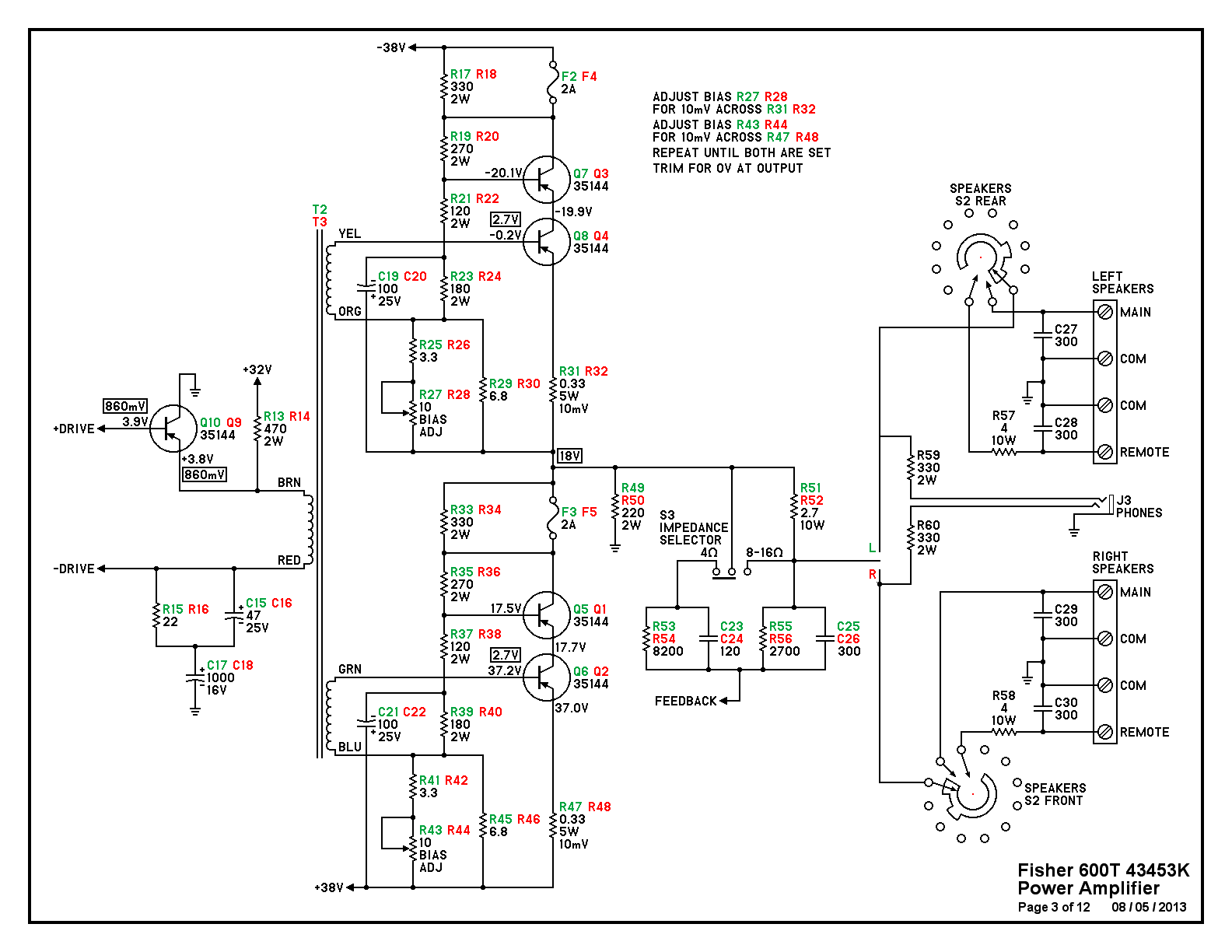
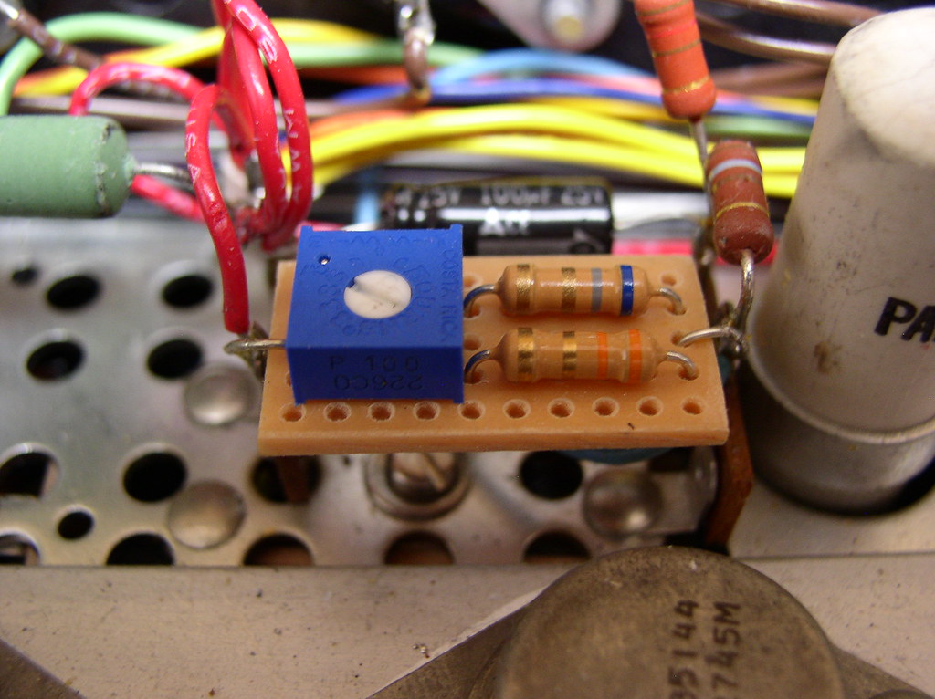
and the revised bias adjustment network .....
1424
Some variations will have 2 different part numbers for the transistors. This is not critical. Also, the resistors in the bias network (R17, R19, R21, R23 and their companions) may vary from what is shown here. There are 2 keys to this modification. One is (R25, R27, R29 and its companions), the other is (R31, and its companions) the emitter resistors.
The emitter resistors should be 1%, not because the circuit is that critical, but the measurement is. This is where the bias current will be measured. The bias adjustment network resistance is "trapped" by R25, R29, and R27, such that this combination must be between 2.5 ohms and 4.5 ohms even if the pot wiper should lose contact. The sealed Bourns pots should be reliable and the small size is not an issue. There is very little power dissipated and no real need for those original large wirewound units.
Adjusting Bias
Connect a voltmeter across one emitter resistor and adjust the associated trimpot for 10 mV, corresponding to 30 mA of emitter current. Turn the other trimpot in that channel to approximately the same physical position because the adjustments for the upper and lower transistor pairs interact and this will get the adjustments closer to start. Actually, you could start with both pots adjusted to mid range. Then check the voltage at the other emitter resistor. Repeat until both are adjusted. Next, the DC output offset voltage should be measured. If it is positive, then the upper transistor pair needs slightly less bias and the lower slightly more. If the voltage is negative, then the opposite. This is a very small adjustment.
Let the amplifier "cook" for a while, then recheck the adjustments.
ODYOFAEL
The Voice of Vintage HiFi
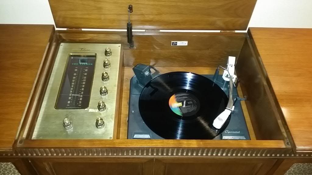
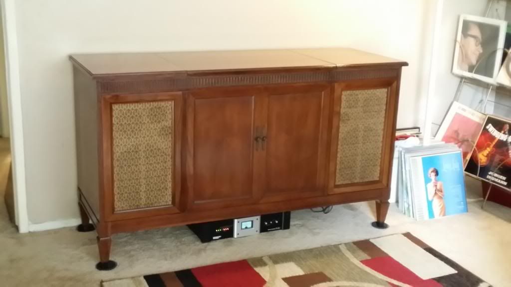
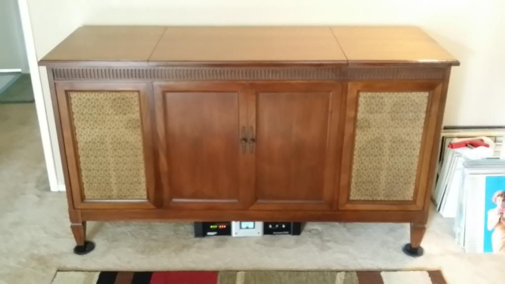
Finally got her up and running.
Thanks to all who replied to my thread. I've been busy with work and had to put my priorities first on the line or I won't have money for this hobby.
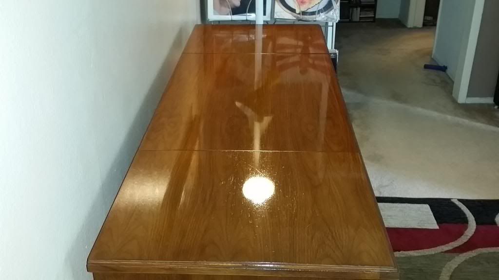
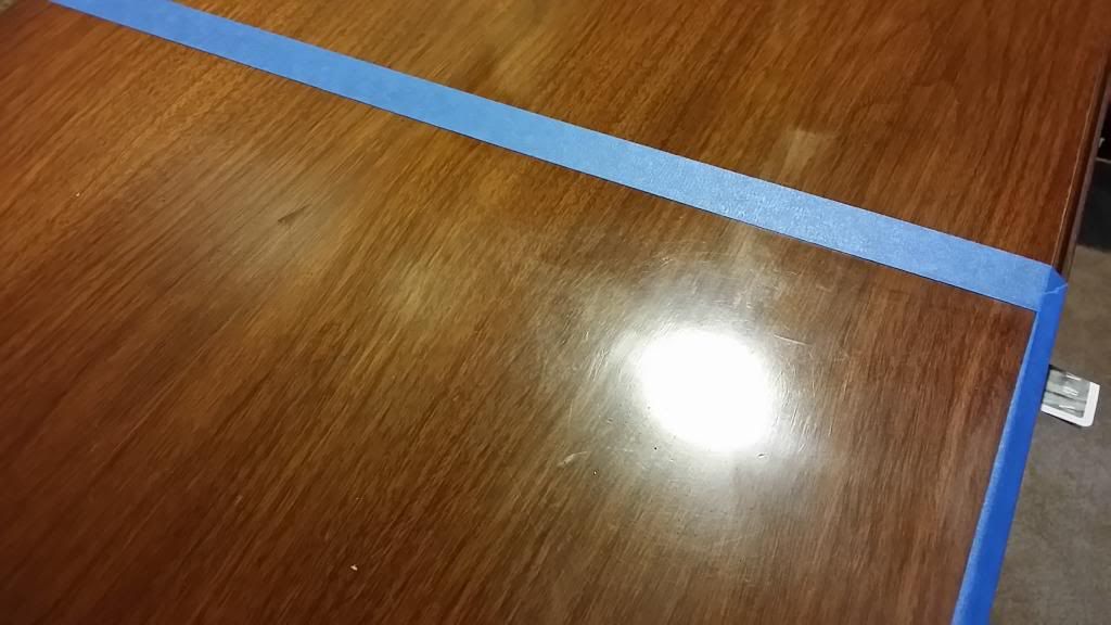
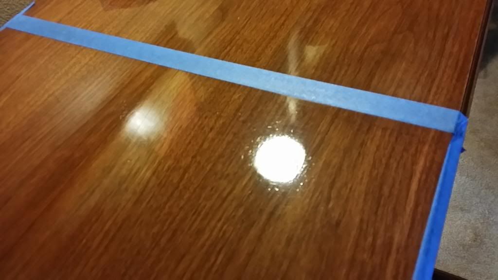
So the SOP, deoxit, check voltges, tubes. All checked out except for four weak output tubes and a 6BE6. She still has all the original tubes surprisingly. I also did some machine buffing on the top.
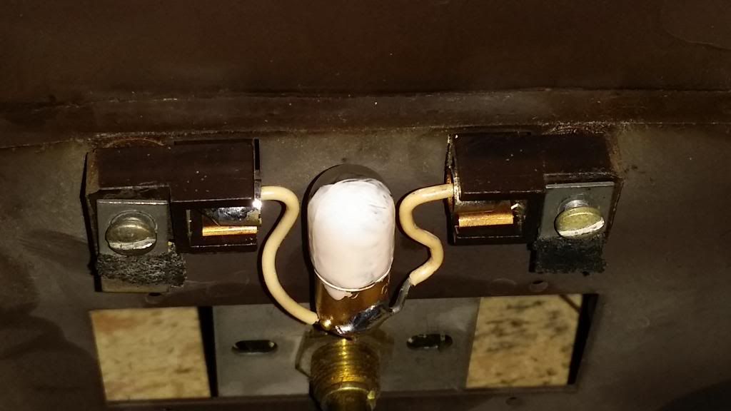
I had to do some mods on one of the missing dial lamps so McGiver to the rescue.
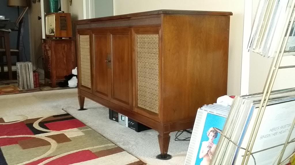
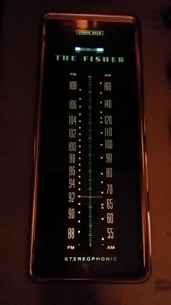
She is singing...here she is. My gorgeous 1963 Fisher FUTURA F58.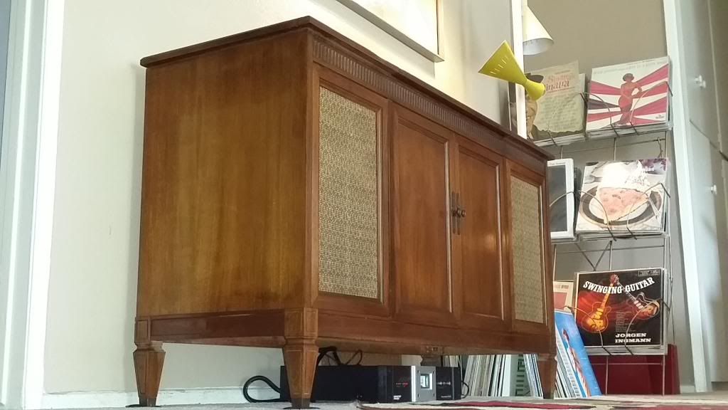
Thanks to all who replied to my thread. I've been busy with work and had to put my priorities first on the line or I won't have money for this hobby.
So the SOP, deoxit, check voltges, tubes. All checked out except for four weak output tubes and a 6BE6. She still has all the original tubes surprisingly. I also did some machine buffing on the top.
I had to do some mods on one of the missing dial lamps so McGiver to the rescue.
She is singing...here she is. My gorgeous 1963 Fisher FUTURA F58.


Looks great! I still like the Provincial, too. Seems those were the ones chopped up so the modern cabinets seem to have a better survival rate. I look at it as though the Provincial is the rarer bird now.
As for the buffing--lacquer is the BEST! So forgiving and you can really restore a beautiful factory finish. Put a good coat of Carnauba wax on it!
As for the buffing--lacquer is the BEST! So forgiving and you can really restore a beautiful factory finish. Put a good coat of Carnauba wax on it!
frankxbe
Super Member
She is singing...here she is. My gorgeous 1963 Fisher FUTURA F58.
Very nice :thmbsp: Oh the radio in the background Grundig or Saba ? working?