
The LME4990 I very popular, as the OPA2134. I also like LM4562. Lots of people denigrate the NEC 5532 but t's a good sound also - it's used in the highly regarded Vista Audio.. The OPA627 is supposed to be very nice but it's pricey - you need 4 and they are about $30 each. Personally I keep coming back to the LME49990. Most are cheap enough to try several

You are using an out of date browser. It may not display this or other websites correctly.
You should upgrade or use an alternative browser.
You should upgrade or use an alternative browser.
Another Super High End Phono Stage! No expense spared...
- Thread starter Fasterdamnit
- Start date
skrodahl
Active Member
WOW ! My 2000th post.
Congrats, and thanks for all your helpful posts.
skrodahl
Active Member
There's another thread as well, with opamp-rolling and comparison to the Hagerman Bugle:
http://www.audiokarma.org/forums/in...re-amp-opamp-rollng-and-bugle-comparo.387282/
http://www.audiokarma.org/forums/in...re-amp-opamp-rollng-and-bugle-comparo.387282/
babblefish
Active Member
Received the boards today, thanks to www.muffsy.com! Very high quality boards, I must say.
Time to start gathering parts then. Digging through my stash, I came across a couple of these Analog Devices ±15v, 100mA power supply modules that I forgot I had. They have direct AC input so no power transformer is required. Ripple/noise is spec'd at 0.5mV RMS at max output. Output impedance is 0.2Ω at 10kHz. Should do very well for this projects' power requirements. Size wise, they're just a little bit bigger than the boards themselves.
My plan is to eventually mate this phono preamp with a vacuum tube SRPP preamp stage designed by Bruce Heran, with both sharing the same chassis. Kind of a poor man's ARC SP-9, if you will. I may incorporate a valve phono stage, also designed by Bruce into the same chassis. This would allow me to switch back and forth between SS and valve phono stages. Why? I have no idea, just because I can I guess.
Not sure if I'm allowed to mention another website here, so I won't. If anyone is interested in getting more information on Bruce Heran's designs, PM me.
Attachments

babblefish
Active Member
Ok, my head is about to explode. I've been trying to source the capacitors and while I was at it, do some research on the differences between the various WIMA types, i.e., MKS (polyester), MKP (polypropylene), FKP (polypropylene), FKS (polyester), etc. It turns out that many so-called audiophiles do not like WIMA, but if they had to use them, they would only use the MKP version. They site the slurred upper frequencies that WIMA (especially the MKS version) caps cause. Fine, I go look for some MKP versions. Problem; the lead spacing (pitch) for these are greater than the PCB allows for. Fine, many have high praises for the Rifa caps or Siemens MKV type caps. Problem; the lead pitch for these are even wider than the MKP and their pricing makes my wallet go running away screaming. So, WIMA MKP2/4 it is. Now to figure out if the ones' offered on eBay from Asian suppliers are real WIMA or not and a way to squeeze them onto the board.
Anyone else have any feedback on their capacitor experiences?
Anyone else have any feedback on their capacitor experiences?
skrodahl
Active Member
I refuse to get into a lengthy discussion about capacitor sound, as that leaves no winners. ")
That said, I stand firmly in the camp with those who say capacitors (when used right) have little to no effect on the sound. Doubly so when it comes to higher frequencies, as the physical properties of a capacitor is to let those through.This is not the subject here though, let me explain:
The RIAA equalization filter in this circuit is passive. No part of the signal (that comes from your turntable, through the phono preamp, through to your preamp/amplifier and make your loudspeakers move) passes through these capacitors. To illustrate this, here's the schematic. R1, R2, C1 and C2 form the RIAA equalization filter:
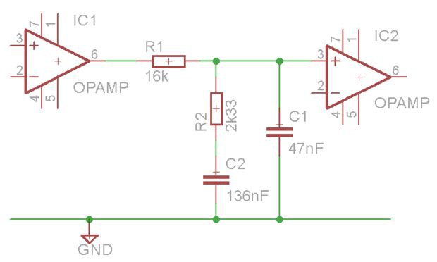
The signal passes through R1, the equalization is applied by leading part of the signal to GND depending on frequency, the remaining signal goes through to the output.
The signal does go through the output AC coupling capacitors though. The board has holes for both 5 and 10 mm width output capacitors, which leaves you with quite a range of options. The signal will never exceed more than a couple of volts, and it will never be more than a few milliamperes.
Old Russian paper in oil and large MKP audio capacitors won't fit. That was one of my design decisions when creating the PCB. Should you decide to fit a larger capacitor, chances are that the longer exposed component legs will introduce more noise and have a larger effect on the sound than replacing the cap will.
That said, I stand firmly in the camp with those who say capacitors (when used right) have little to no effect on the sound. Doubly so when it comes to higher frequencies, as the physical properties of a capacitor is to let those through.This is not the subject here though, let me explain:
The RIAA equalization filter in this circuit is passive. No part of the signal (that comes from your turntable, through the phono preamp, through to your preamp/amplifier and make your loudspeakers move) passes through these capacitors. To illustrate this, here's the schematic. R1, R2, C1 and C2 form the RIAA equalization filter:
The signal passes through R1, the equalization is applied by leading part of the signal to GND depending on frequency, the remaining signal goes through to the output.
The signal does go through the output AC coupling capacitors though. The board has holes for both 5 and 10 mm width output capacitors, which leaves you with quite a range of options. The signal will never exceed more than a couple of volts, and it will never be more than a few milliamperes.
Old Russian paper in oil and large MKP audio capacitors won't fit. That was one of my design decisions when creating the PCB. Should you decide to fit a larger capacitor, chances are that the longer exposed component legs will introduce more noise and have a larger effect on the sound than replacing the cap will.
skrodahl
Active Member
Digging through my stash, I came across a couple of these Analog Devices ±15v, 100mA power supply modules that I forgot I had. Ripple/noise is spec'd at 0.5mV RMS at max output.
I just did a calculation of the effect of a 1 mV power supply ripple on the OPA2134 which as a PSRR of (typ) 106 dB. The effect on the output signal is 0.00000018 volts. It goes without saying that your power supply will be a great fit with this phono stage.
babblefish
Active Member
Thanks for your thoughts concerning the capacitors. and I understand your comments regarding the RIAA filter, but, I have heard differences in capacitors when used in a coupling situation though. I do have some Rifa caps, but like much of my other electronic components, they are sized (working voltage) for vacuum tube circuits, so tend to be quite large. Since everyone else seems to be perfectly happy with the sound of the polyester (MKS) version of the WIMA caps, I'll throw my hat into the same ring and use them....though I may play around with that output cap...just for educational purposes you understand...
Regarding the PS, I remember having at least a half dozen of them at one time, but threw away all but two because I thought I'd never use them...sigh. I should stick to being a pack rat.
Regarding the PS, I remember having at least a half dozen of them at one time, but threw away all but two because I thought I'd never use them...sigh. I should stick to being a pack rat.
Grainger49
Old Fart
I'm in the camp of capacitors do make a flavoring difference in the sound. Most especially those in the audio path. That would be the output capacitor for this circuit. A number of AKers have used Kommie Kap (KK) PIO, K75-10 being the ne plus ultra, for output caps. Often these are bypassed with KK Teflons. I like these for their bang for the buck. But they are bulky.
In the RIAA circuit, it is more important to get the value spot on so the EQ is right. That applies to both the capacitors and resistors.
Now I'm not saying that different capacitor make up doesn't change the sound of the RIAA EQ. I'll have to wait till I put in some dead on Multicap RTX caps I bought from Sonic Craft into my BH Eros. I have been influenced by a local friend. I spent $85 for the set and they are exactly the value specified. Yes, I'm a sick puppy.
Last edited:
skrodahl
Active Member
Just to clarify,
I'm not saying that capacitors don't affect the sound, just that I haven't found any evidence of it. There may very well be good reasons for using other output caps, or RIAA caps for that part. That's for everyone to decide, it is DIY after all.
One of the disadvantages of my PCB, compared to Sachin's is that mine doesn't have much room for other audiophile/boutique components than resistors in the audio path and the RIAA filter. That was a conscious choice on my part, based on nobody's requirements but my own. I wanted a smaller board that fits in the enclosure I'm using. That gives shorter signal paths, and the ability to maximize the production quality at a somewhat reasonable price.
I'm with Grainger on the importance of matching the values so that both channels are equal. And there's no denying that one of the best aspects of DIY is the ability to go completely over board with regards to the components. More is definitely more in this case.
To bad you threw away those power supplies though. I've had a look at them many times, but they are really expensive.
The RIAA equalization filter in this circuit is passive. No part of the signal (that comes from your turntable, through the phono preamp, through to your preamp/amplifier and make your loudspeakers move) passes through these capacitors. To illustrate this, here's the schematic. R1, R2, C1 and C2 form the RIAA equalization filter:
The signal passes through R1, the equalization is applied by leading part of the signal to GND depending on frequency, the remaining signal goes through to the output.
That is incorrect. C1 and C2 form potential dividers (albeit frequency dependent ones) with R1 and R2. The capacitors are just as important as the resistors. The idea that they aren't "in the signal path" is quite simply incorrect.
The definitive work on capacitor distortion was conducted by Cyril Bateman. A google search will find it easily.
Grainger49
Old Fart
. . . Digging through my stash, I came across a couple of these Analog Devices ±15v, 100mA power supply modules that I forgot I had. They have direct AC input so no power transformer is required. Ripple/noise is spec'd at 0.5mV RMS at max output. Output impedance is 0.2Ω at 10kHz. Should do very well for this projects' power requirements. . . .
When you have finished you might find that there is no DC offset at the output of the second stage. If so you can replace the output cap with a jumper. The Op-Amps have a tiny DC offset. The cap is there for the stock batteries which will almost never be at the exact voltages as they wear down. Probably not even when they are new. That causes a DC offset at the outputs. The AD power supplies will be well matched.
skrodahl
Active Member
That is incorrect. C1 and C2 form potential dividers (albeit frequency dependent ones) with R1 and R2. The capacitors are just as important as the resistors. The idea that they aren't "in the signal path" is quite simply incorrect.
The definitive work on capacitor distortion was conducted by Cyril Bateman. A google search will find it easily.
Is this one of my logical breakdowns? Again?
The caps affect the signal, no doubt about it. But does the end signal pass through them? Does it matter that it doesn't?
I can see that caps that have frequency dependent capacitance will affect the frequency response though.
babblefish
Active Member
When you have finished you might find that there is no DC offset at the output of the second stage. If so you can replace the output cap with a jumper. The Op-Amps have a tiny DC offset. The cap is there for the stock batteries which will almost never be at the exact voltages as they wear down. Probably not even when they are new. That causes a DC offset at the outputs. The AD power supplies will be well matched.
While you are probably right, I'd want a cap there anyway, just in case of a failure of one of the IC's. I look at it like wearing suspenders with my belt, one never knows...
babblefish
Active Member
Concerning the caps in the passive RIAA filter, while I feel that rothwellaudi is correct, I'm wondering how much difference it really makes in real world listening, assuming the correct value caps are used, of course. I'm thinking that as long as the values are correct, giving an accurate RIAA curve, any changes to the sonic value of the pre-amp (which may not be measurable) by using different types of caps is highly dependent upon the person listening to it whether the changes are good or bad. It's that old Pepsi or Coke argument.
Last edited:
Is this one of my logical breakdowns? Again?
The caps affect the signal, no doubt about it. But does the end signal pass through them? Does it matter that it doesn't?
I can see that caps that have frequency dependent capacitance will affect the frequency response though.
We can simplify things to aid the imagination. Consider two resistors forming a potential divider instead of a resistor and capacitor. You will often see such an arrangement drawn with one resistor horizontal and one vertical (down to ground), and this leads people to think of the signal passing through the horizontal resistor and nothing more than "waste" dropping down through the vertical resistor. This is not what is really happening. Consider instead the same circuit re-drawn with both resistors vertical. Also, for simplicity, consider that both resistors have the same resistance. The voltage at the halfway point is half what it is at the top. What would happen if one of the resistors was somehow "off value"? The half voltage point would also be "off value". If one resistor distorted the signal, the half voltage point would also show distortion. Does it matter if it's the top resistor or the bottom resistor which is faulty? No, they're both equally important. The idea that the signal passes through the top resistor and exits at the halfway point without having anything to do with the bottom resistor is just plain wrong. The more you think about it, the more you'll realise that it's true. You'll realise that most of the stuff said about "the signal path" is total nonsense.
The same logic applies if you replace one resistor with a capacitor.
Check out the Cyril Bateman research. To summarise, ceramic caps don't distort as long as they're the right type. Polypropylene caps don't distort, but polyester do. Polystyrene don't distort. Electrolytics are the worst, but there is a workaround - use huge ones with virtually no signal voltage across them.
That's all just a very, very brief summary of the research. The complete findings were published over several months in ETI and it was very comprehensive work.
That's all just a very, very brief summary of the research. The complete findings were published over several months in ETI and it was very comprehensive work.
Similar threads
- Replies
- 47
- Views
- 8K