Martinihenry
New Member
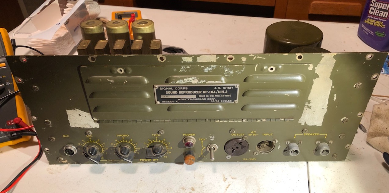
I recently came into one of these olive-drab "Public Address and Sound Reproducer" amplifiers, but it needs service. Unfortunately, I cannot find a schematic for the blasted thing anywhere.
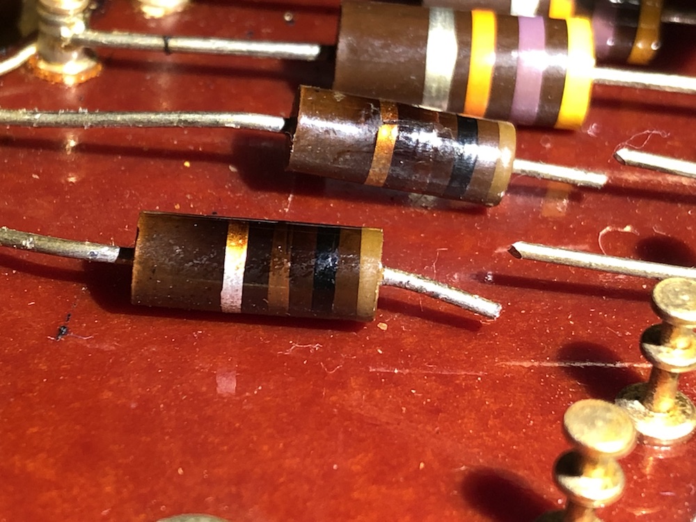
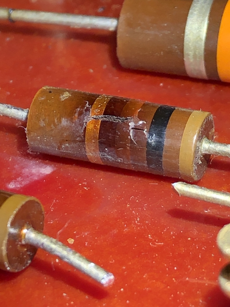
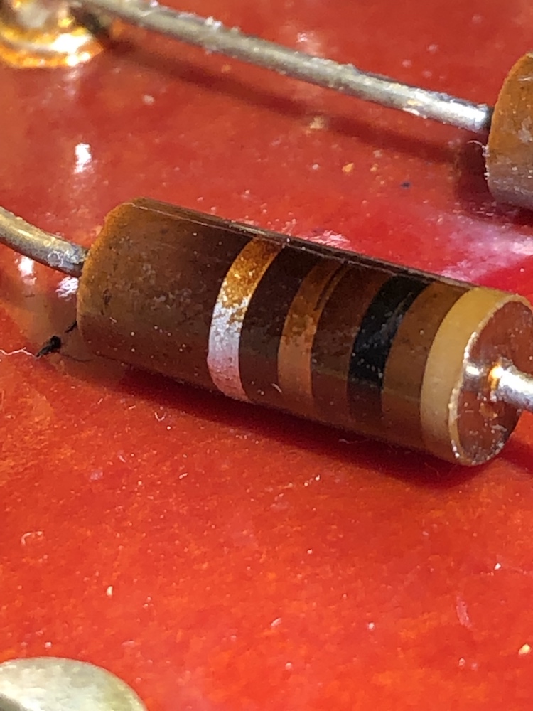
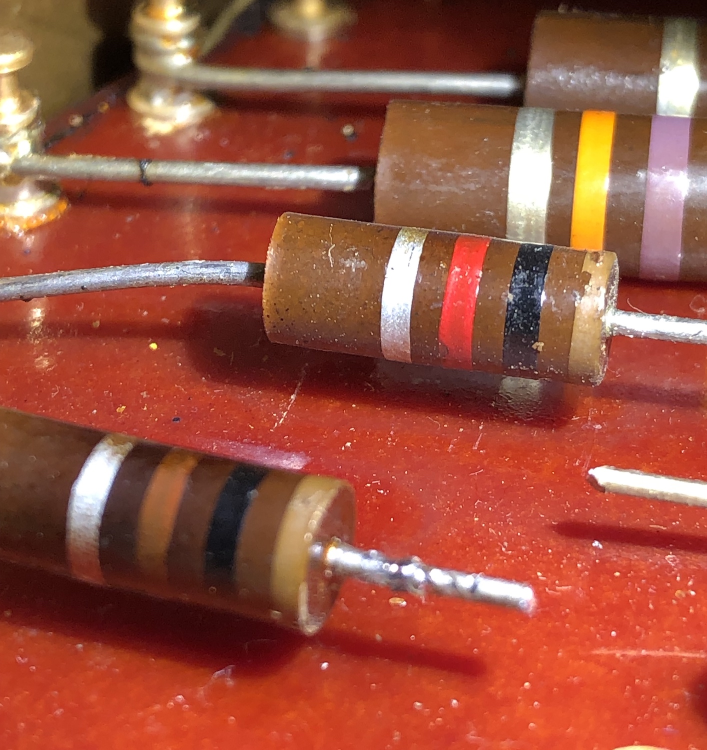
One of the metal-can capacitors blew, and took out a couple of carbon comp resistors, and baked a couple more to the point where their color-code value is just not legible.
There are copies of service manual online, yes, but during the scanning process, they neglected to fold out the schematics, and wiring diagram foldouts, so you only see a small slice of them...not enough to glean the information I need to repair the amplifier. They didn't even scan the parts list for crying out loud.
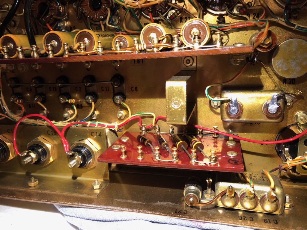
OR....if anybody has one of these, could they please, please, PLEASE take a picture of the small circuit board containing 4 large carbon comp resistors so that I may determine their values? I've attached a photo of the small circuit board in question. Believe me, the values are not legible, despite how it looks in this photo.
The cap that blew is the 50µF/50V cathode bypass cap bolted to the chassis, just above and to the right of the resistor circuit board. I gutted it and restuffed it with a modern cap (after scraping and cleaning up the potted tar that blasted all of the chassis). Oddly, this didn't appear to be an oil filled cap, it had a gummy black tar inside, like old Philco bakelite block caps.
Thanks!
One of the metal-can capacitors blew, and took out a couple of carbon comp resistors, and baked a couple more to the point where their color-code value is just not legible.
There are copies of service manual online, yes, but during the scanning process, they neglected to fold out the schematics, and wiring diagram foldouts, so you only see a small slice of them...not enough to glean the information I need to repair the amplifier. They didn't even scan the parts list for crying out loud.
OR....if anybody has one of these, could they please, please, PLEASE take a picture of the small circuit board containing 4 large carbon comp resistors so that I may determine their values? I've attached a photo of the small circuit board in question. Believe me, the values are not legible, despite how it looks in this photo.
The cap that blew is the 50µF/50V cathode bypass cap bolted to the chassis, just above and to the right of the resistor circuit board. I gutted it and restuffed it with a modern cap (after scraping and cleaning up the potted tar that blasted all of the chassis). Oddly, this didn't appear to be an oil filled cap, it had a gummy black tar inside, like old Philco bakelite block caps.
Thanks!
Last edited: