Beginning a 500-T Restoration - Expertise requested

buffdriver

Active Member
Hello,

This is my first post in the Fisher forum--my previous work has mainly been with Pioneer components.

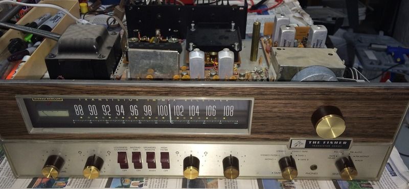
I'm beginning a restoration on a Fisher 500-T for a friend. It's a really nice receiver.

IMG_4176.jpg


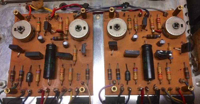
He reported that the left channel is out, and I've verified that Q4 is blown and Q3 is close to failure. I then removed the heat sink for the left channel driver and saw that CR851 appears damaged/swollen.

IMG_4175.jpg


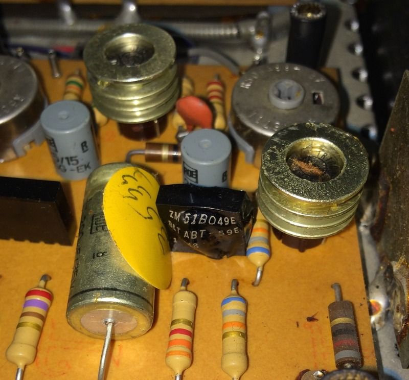
CR851 appears to be a combination diode and zener in a single package.

I know that I have more work ahead to determine other damage and/or inoperative components, but this one jumped out at me and has me puzzled as to how to replace it. Is this part replaceable with a modern equivalent?

BuffDriver
 
I've got distorted one's like that on my 700-T. The driver boards are the same between the 500-T and 700-T with the exception of the suffix. The diode/zener is a 2A10 diode and a 6.8v 1W zener as separate parts. Recap the board, check all the resistors, and make sure those bias and offset pots are working smooth
 
Last edited:
If Q3 and Q4 are out, then drivers Q852 and Q853 could also be bad.

CR851 is overload protection and values are not extremely critical. If you are very careful with the load (maybe add a 4 ohm resistor in series with the speakers while testing), CR851 and CR852 can be left out. They should be reinstalled before returning the unit to regular service.

Be sure that CR5 is good. It should have a voltage drop of approximately 2 V. If it is open, or if R855 and R858 are open or high resistance, the output stage will be biased full on and be destroyed.
 
JD,

I've read your entire restoration thread and know better! This one looks so nice that I may try to talk my friend into a trade. :)

Larry, thanks for the words. If I understand correctly, there may be no cause for alarm with the malformed diode. I will do as you say and bring her up on DBT to check voltages.

I have another question or two if either of you wouldn't mind.

1. I'm planning on replacing all 4 output transistors with ON Semiconductor 2N3055G (Mouser part 863-2N3055G). Does this seem reasonable?

2. When I removed the heatsink on the driver board, some of the transistors were filled with a clear fluid similar to a light oil. The heat sink had sealed the fluid into place. Should they all be fluid filled, and what fluid should be used?

Thanks gentlemen. I'm confident that I can bring her back to life, but I've never worked on anything this old. I appreciate the schooling.

Cheers,

BuffDriver
 
Fred, thank you as well. I will check these things and report back. I would like to limit the number of Mouser orders, so I appreciate any advice for finding other suspect components.
 
JD,

I've read your entire restoration thread and know better! This one looks so nice that I may try to talk my friend into a trade. :)

1. I'm planning on replacing all 4 output transistors with ON Semiconductor 2N3055G (Mouser part 863-2N3055G). Does this seem reasonable?

2. When I removed the heatsink on the driver board, some of the transistors were filled with a clear fluid similar to a light oil. The heat sink had sealed the fluid into place. Should they all be fluid filled, and what fluid should be used?

I'm still wondering how much better a tube Fisher could possibly sound. I love the 500-T so much that I really don't feel the urge to seek out a 500C.

1. Not sure. I struggled to find ANY equivalents for any of the "TR" transistors. That's why I abandoned refurbishing my first 500-T. I try to avoid NTE transistors too.
2. Could this be potting, or epoxy of some kind to attach the heat sink to the transistor? (I assume you are talking about the "TR" transistors with the ring type heat sinks around them).
 
Last edited:
Best bet for the TR's (output's) is mj21196. It's way overkill, but it'll handle anything the 500-T can dish out.

There should not be ANY LIQUID in or on the heatsink or behind or on top of any transistors. There is a silicone based heatsink compound (zinc oxide and silicone grease) that is applied to the backs of the transistors and the MICA insulator spacers (both sides) on output transistors. It is applied in a VERY THIN OPAQUE layer. It fills the microscopic air pockets between the heatsink and mica and then the mica and the transistor.

Same thing with the square heatsink on the driver board. Just a dab of the silicone based "HEATSINK compound. The silicone may have leached out. spread it out very thin and opaque.

JD. What I put in my 700-T it uses the same driver board as the 500-T except for suffix.

TR1004--->KSA1220AYS--->TR1002
TR1005--->KSC2690AYS--->TR1003


TR1009------>MJ 21196---->TR1007
_____________________________________

TR1033-34------>See 1004/1005
BC109------->2N5089
2n4062----------->mps6518

SE4010------>KSC1815YTA
2n2924-------->2n2924
2n2925-------->2n2925
2n3638-------->ksa643

The left set of numbers is from the 700-T 2nd # is Mouser replacement 3rd is 500-T equiv on Driver board.
The rest under the line is stuff on other boards.
 
Alrighty then...

Q852 is bad, Q853 is nearing failure also. I ran the 6-way transistor test after making the most amazing discovery: The 3 transistors on the driver board are SOCKETED!

Many thanks for the transistor substitutions. I've used 2690 many times before and have a couple more laying around. I will have to add the 1220 to my order.

@Larry: If the driver board subs are done, are they okay without the heatsink? Those [edit] TO126 packages often do fine on power amp boards without anything extra. Also, did you remove the entire socket and solder in the replacements. I would think that the replacement legs would be too thick for the sockets.

@fred: CR5 voltage drop is nearly spot on 2V. I haven't tested R855 or 858 yet, but I took readings and neither appears to be fully open or closed. I will continue to investigate before firing up the new transistors.
 
Last edited:
With the TO126 pkg transistors, the heatsink is NOT needed, and you DO have to remove the sockets. Even then the holes are barely sufficient for the 126's legs, so make sure the holes are completely free of solder. And get the datasheets for the pinouts. They will be different.
 
If you are purchasing new transistors, then use the MJ21196 rather than the 2N3055. It is a much newer device with much higher ratings across the board.

For the TO126 transistors, after the holes in the board are cleaned as well as possible, you can use a pin vise and a small drill bit to carefully open up the holes. Do NOT use any sort of power drill for this. If you have a micrometer or drill gauge, you can check the actual size of the transistor leads before selecting the drill bit. The leads are specified as rectangular, 0.5 mm x 0.75 mm. This calculates to a hole size of 0.3549 in. A #65 drill bit is 0.035 in., a #64 is 0.036 in.

FYI: You CAN edit your posts, but it's possible that no one will go back and read them again to catch the edits.
 
I've almost finished sourcing parts at Mouser. What are your thoughts on using radial caps in place of some of the axials?

Radials seem to have several things going for them.
- There are more readily available across the board
- They are available in my favorite Nichicon lines (UPW & UKL, I'm a MTF disciple) for longer life or better noise characteristics
- They are cheaper (not a big concern, but as long as we're considering options...)

The only advantage I see to staying with axials is the fit.
 
I don't see a problem with using radials, other than having to extend the lead(s) on some of them. I very rarely use axials. On a stock amp board using the original transistors and the coverplate heatsinks, you'd really be better off with TVX series. Otherwise UKL's. and UPW's as needed. On sub 4uf caps, use a film cap instead (mainly on the pre-amp boards). Even less noise, no leakage, and you don't have to worry about replacing them in 20 years, plus they sound better than the lytics. ECQ series by Panasonic, or Cornell Dublier DME's are good.
 
Sorry to be so long updating the thread. I had to finish some other projects and get the parts for the Fisher. The driver boards are finished, and it was much easier than I thought.

Drivers.jpg


Larry, thanks for the insight to trust that diode package--it appears fine. I've also replaced the 1ohm 5W output resistors with wirewound and the new ON Semiconductor MJ21196G outputs are in place with new mica and heatsink compound.

Voltages were close, and I set the center voltage and bias according to the service manual. I'm now getting sound from both channels, but it's not yet great sound. In fact there is noticeable distortion from the left channel.

This has been planned as a full recap from the start, so I knocked out the Audio Control Amp 1278-3 with new caps and transistors to see if that might help, but the distortion persists. Next step, power supply.

I decided to restuff the four largest caps, and began with the coupling caps using Nichicon UPW 2200uF 63V radials:

Restuffed%20Cap.jpg

Coupling%20Caps.jpg


Edit: There is a mistake in the photo above. I had the bright red wire on the left hooked to the positive instead of negative terminal. It's now fixed.

That's where I am at the moment. Later this weekend, I want to finish restuffing the main filter caps and then begin replacing the other power supply caps with axials. I'm replacing the 2200uF with a Nichicon UKW 3300uF 100V radial, and the 1000uF will be restuffed with a UPW 1000uF 63V radial. I will post a followup when finished.
 
Last edited:
Okay, I finished most all of the power supply, but the distortion is still present. Dumb $#& me remembered that I had problems setting the bias on the right channel, even before the power supply work. No surprise, the problem is still there.

Power supply voltages look good. Left channel calibrates nicely. I've done the 6-way check on the right channel outputs and they test fine. Both driver boards have all new transistors and capacitors. Here are voltage readings for Q851, 852, and 853 on both driver boards:

Left (appears normal)
Q851
B 2.1 V
C 29.1 V
E 1.6 V

Q852
B 32.0 V
C 61.7 V
E 31.8 V

Q853
B 30.0 V
C 0.6 V
E 30.7 V

Right (appears that Q853 is in cutoff)
Q851
B 2.1 V
C 27.2 V
E 1.6 V

Q852
B 30.1 V
C 61.7 V
E 32.0 V

Q853
B 27.9 V
C 0 V <-----------
E 19.1 V <-----------

Any ideas on what might be going on?
 
Check the emitter resistors (1ohm 3w), check R863 for value and continuity, plus the diode pack CR855. Did you check the pots for smooth response with a meter? If it shows an open or is dirty it will inhibit or prevent adjustment.

Do you have a scope? If so inject a 1khz tone at the AUX input and scope the response at each component starting from the output to the input. If you still have a distortion by the input, suspect either tone control board, predriver, driver, or Eq board. You'll need to go thru each board until you get a clean sine wave.
 
Last edited:
Thanks, Larry. If I understand the emitter resistors, you are talking about R37-R40, and I replaced them, though I thought they were 5W. I pulled R863 and it tests only slightly out of spec at 73 ohms (68 expected). CR855 checks good, but did you mean CR852 when you said "diode pack"?

As for the pots, I originally thought that the bias pot was bad, because the bias reading was 0 volts with no change turning the pot; however, there is a secondary check for bias, which is 2.3 V across the base of Q852 and Q853. When using that method, the bias pot provides very smooth response, so I don't think it's faulty.

I do have a scope, but can't really work on the distortion now as the driver board is disassembled. My next thought is that CR852 may be faulty. How would I check that? If it needs replacing, you've already supplied the information above that I can replace it with a 2A 100V diode and a 6.8v 1W zener. Would I look for a switching diode or a rectifier?

Edit: One last piece of info - When setting center voltage, the right (faulty) channel doesn't want to settle down. I can set it to zero, but it slowly wanders. If it's positive and I set it to zero, it slowly goes negative. If I reset it to zero again, it slowly moves positive.
 
Last edited:
Back
Top Bottom