Bose 1800 pair, not quite

blhagstrom

Mad Scientist, fixer.
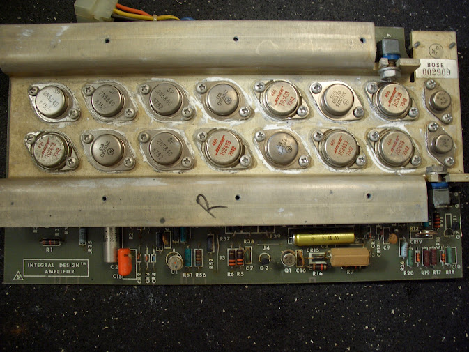
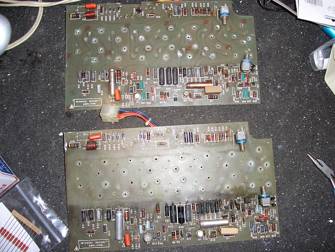
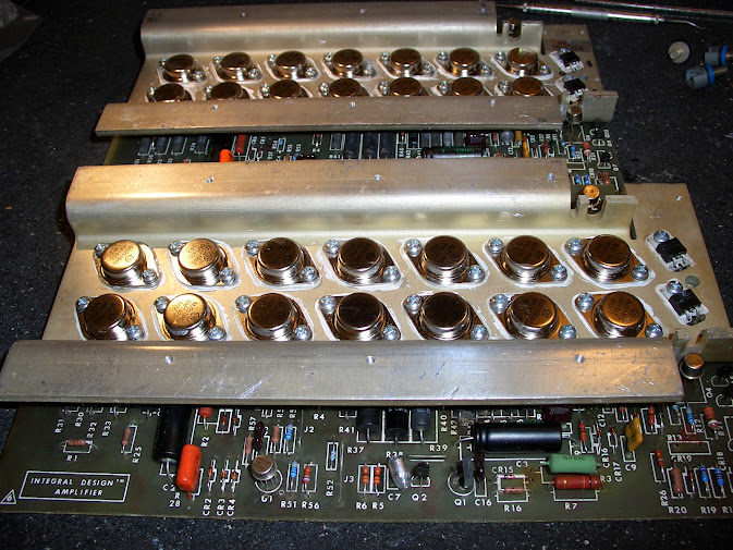
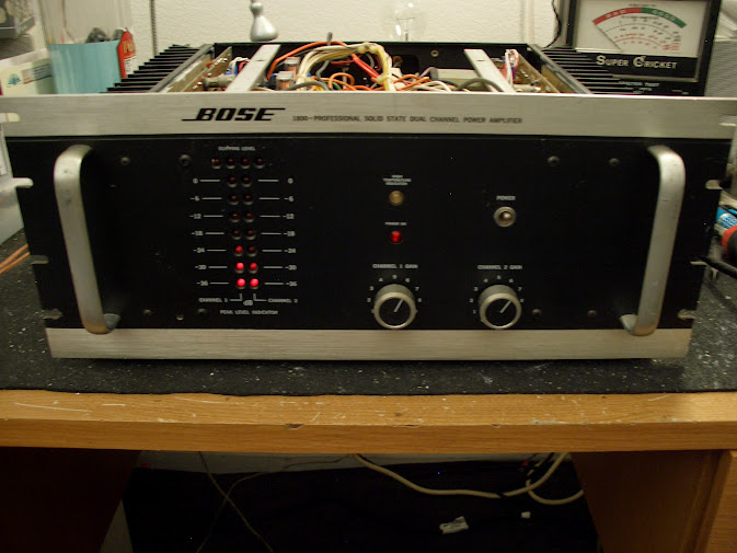
Had a couple monsters show up at the house today from another AK're.

Rebuilding is the plan.

Looks like two versions.

CIMG2237.JPG


CIMG2238.JPG


CIMG2239.JPG


CIMG2240.JPG


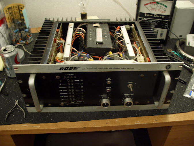
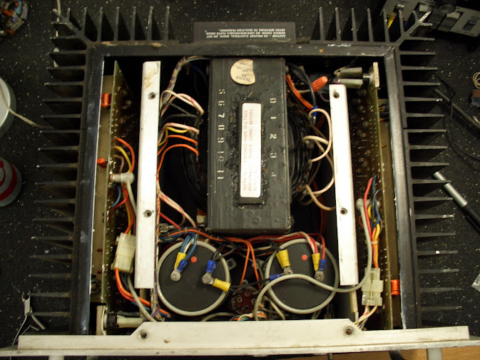
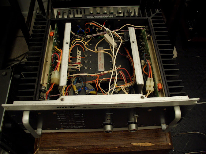
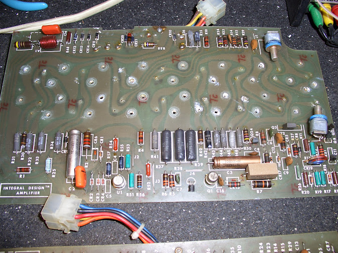
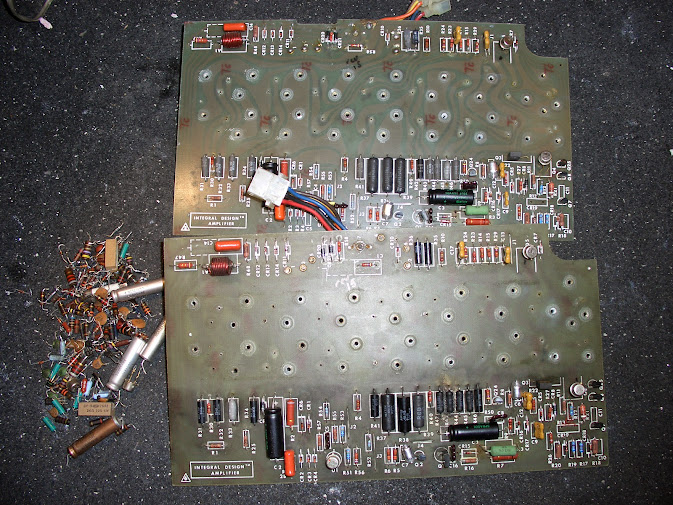
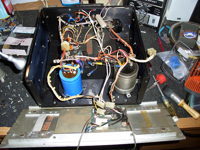
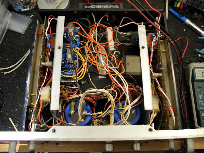
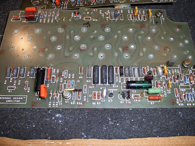
I fixed up my 1801 and it was like the first one. Typically big iron transformer. The second one was a surprise. I was wondering why it was lighter.

Still a lot of heavy! I certainly get a workout fixing stuff around here.
 
tear down

I got amp 1 opened up and found some previous work.

CIMG2242.JPG


THIS is a good reason it has issues and why you want to find a GOOD tech. Yes, they missing soldering in an output transistor!

CIMG2243.JPG
 
Interesting unit. Impressive rack of transistors.. wonder what the watts output and consumption is?

I wonder how many newbies would have just plugged it in without checking it out.
 
250wpc 8 ohm.
400wpc 4 ohm.

Typical power draw, 1kw.

Weight, 80 lbs.

Owner reported one would blow the main fuse.
Who ever worked on it :screwy:
The start relay feed line 10 ohm resister is out.
So they just wired direct to transformer.
I imagine the surge takes out the fuse.
Cord was ratty so I replaced it and checked related parts.

It came up fine on DBT and played briefly.
 
Hmm, gotta learn French.
Where is that translate button....

You run 220v, yes?

I think there is a translate button on the right sidebar. Anyway if you're using Google Chrome you can right click anywhere on the page and chose "Translate into english"

Yes, here on the old continent we are running 230V.
 
Got a pile of parts in and got time in on the amps.

Stripped them down and replaced all the carbon comp resisters diodes, zeners and ceramic caps. Vetted the transistors that stay and replaced those that are available.

Before

CIMG2493.JPG


After

CIMG2495.JPG


CIMG2492.JPG


Its a PILE of parts replaced, see left of boards.

CIMG2494.JPG


Work double checked. There are some resisters not called out in the threads on rebuilding and the SM is known to have errors. SO far the SM schematic is a match. These boards appear to have the rev 15 already but not the thermal stability mod (yet).
 
Had to back track to pick up the thermal stability mod from the service bulletin #17.

Time to install the outputs. New MJ211194G all around.

CIMG2681.JPG


Pretty.

CIMG2683.JPG


CIMG2684.JPG


The TO-66 drivers are replaced by TO-220 MJE15034G and MJE15035G

CIMG2682.JPG


Adding a DC offset adjustment. Connect a 10K trimmer across NULL pins 1 and 5 with the center adjuster connected to Vcc, pin 4.

I'll string wire up and mount the trimmers where they can be accessed. Same with the Bias adjuster.

Bose engineer design, Bah!
 
Working on the chassis. New filter caps installing.

CIMG2686.JPG


Fast forward past a LOT of fitting to get the speaker protection system installed along with the bias and DC offset trimmer access mounted.

The LED display was whacked, so 1/2 of that was rebuilt.

Note that I installed a secondary transformer for the protection boards.

CIMG2688.JPG


This is the reason I decided to re-work the one with the "pancake" transformer. There is room to get the extra parts inside the case. The other style transformer is too large. It takes ALL the case.

CIMG2238.JPG


After a bit (LOT) of fine tuning and tweaking and a couple corrections.

FINALLY! :banana:

CIMG2789.JPG


Both channels stable at 90ma and <1mv DC offset.
 
I know it's an old thread but how did you get the speaker protection boards and transformer in the one with the big transformer?

Have one just like it and can't really find a place for it, next to that huge magnet...
 
Hi all, I am absolutely "new" so i apologize if i make any mistake. Also for the language, couse i am Italian.
So, i know that it's an old thread too, but i am trying to repair a 1800 old series and i am having troubles.
First of all i would like to ask to blhagstrom about the choice to substitute the 2N5840 (impossible to find) with mj211194g (impossible to find too, is the code correct or there is number too much?) so which kind of finals can i use? Reading the datasheets i found BUY69A that seems to be good for that reason, and are enough cheap and easy to find. What do you think?

Other question, but i don't know if i have to open another thread for it:

Channel 1 is ok, channel 2 have a current of 80V in the out (speakers). Every transistor seems to be ok. I have no more idea what to test on.
Can someone help me?
(i have the service manual and the bulletins but in any case i found a troubleshoot to my question

Thanks
 
mj211194g

Welcome to AK! The ON Semiconductor part number is MJ21194G, but I do not know if it is suitable for the Bose. (I would guess that it is suitable, but I cannot speak from experience.)

Ciao,

chazix
 
Hello chazix, thanks for the quick reply.
Now that I have seen the datasheets of the correct code, I understand that the new one is "stronger" than the old one.
However, the fact that it was used by blhagstrom makes me sure it is perfectly compatible, traceable, even if it costs about $ 6 each!

Now I'll wait to find the failure in my amp. I will verify every single component, to finally discover that the problem is elsewhere! Hoping to find a good soul that can help me.

Greetings
 
Last edited:
Channel 1 is ok, channel 2 have a current of 80V in the out (speakers). Every transistor seems to be ok. I have no more idea what to test on.

Hi there !

You are lucky : with one working channel you can always compare voltages of the bad channel against voltages in the working one.
As I have been there and done that many times with this amp, and since you say that all output devices are OK (are you 100% sure ?) I would advise to first check that there's no bad solder joints around U1, C1, CR21, CR20, and R58. Also check R51, R52 and R54 (feedback loop).

Good luck and be carefull, voltages in this thing can be lethal.

Thierry
 
IS c1 is a resistor?????? (EDIT: found in the MB)
In the electric scheme it is a condensator 0.1 uf 100v, and in the PCB is reported as R28, not present in the service manual (edit: found in the scheme from pin 2 of u1 and ground ). The same is in the other channel, that works.
In any case i do not understand the meaningh of the scheme in the input.
Pratically around point 7, ampli input, there is a round line that is ground linnked. Why?! pin 3 of U1 is 0.22 Ohm grounded, is it correct? (edit in next post)
The scheme is such a mess....
 
Last edited:
The history goes on:
I have not a variac, so i tried ti power the MB with a 33+33V from another supply. This was to see about some components, so i've seen that U1 works, i had a 6.5 Vpp signal (distorced!) for an input of 1,75Vpp.
No good signal in the output. 1V about.
I tested at base of Q6 and Q9, and a low signal is present, and also at the "speaker out" and i have only 1Vpp, but i suppose it is because i had not enough Voltage. In fact the voltage in Q1 that is supplyed by the 2 zener, did not arrived not even to his 16V but stopped at 14.
Tomorrow i will test again with the normal 85+85, the MB out of case. I will see...

PS i have 2 power transistor missing Q13 and Q 21, i have shorted the collector contacts each other to guarantee the continuity of circuit. I think it will work anyhow. Doesn't it?
 
Back
Top Bottom