Building a Rod Elliot ESP-P3A Amplifier

mikte15

Active Member
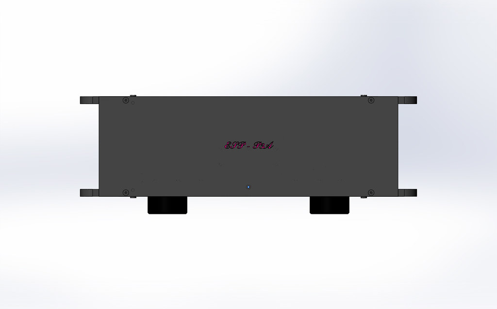
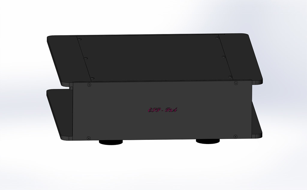
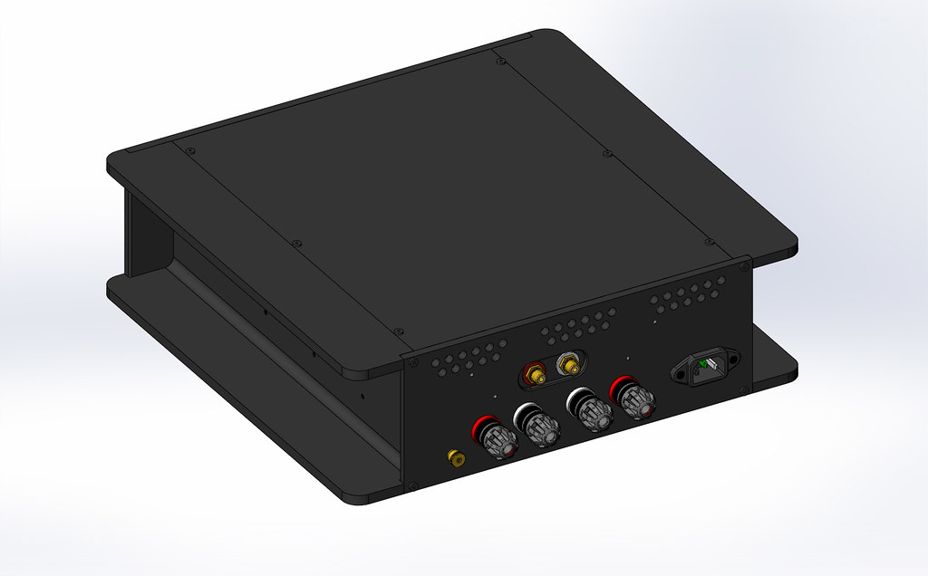
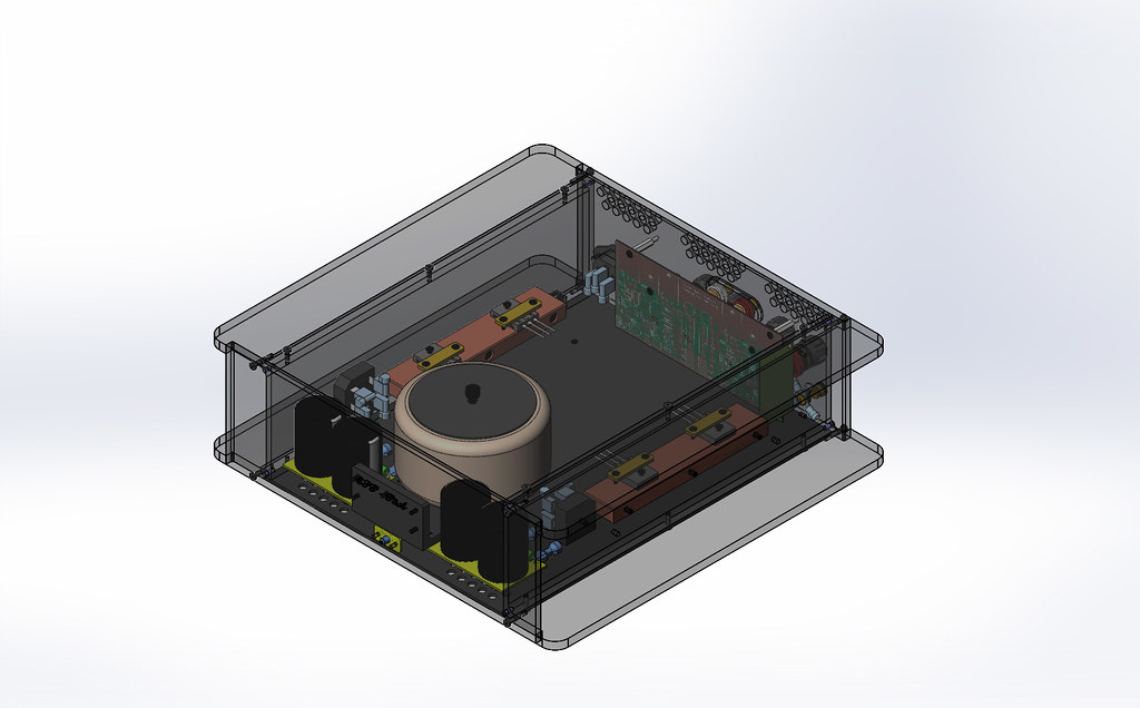
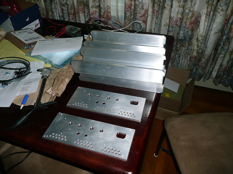
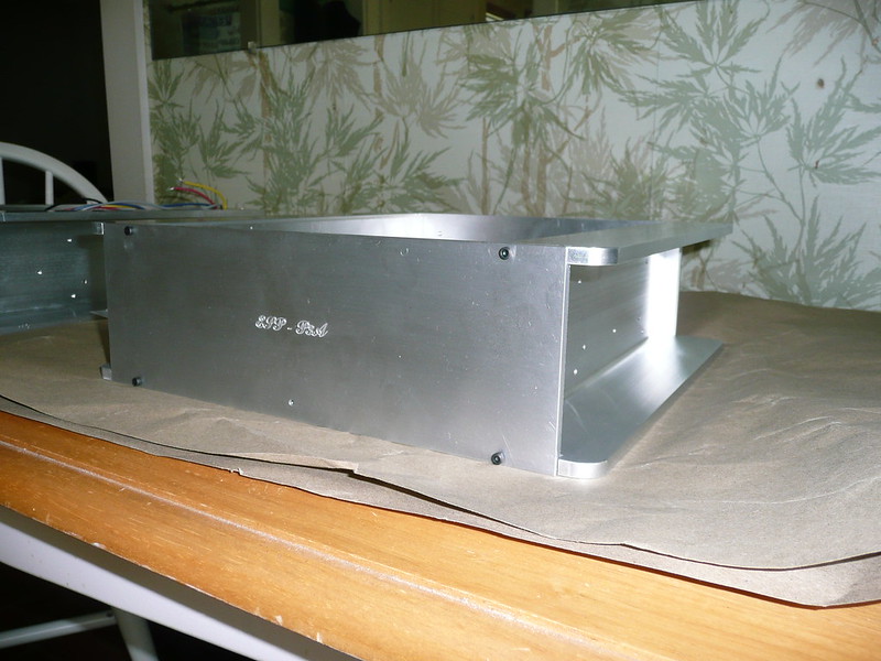
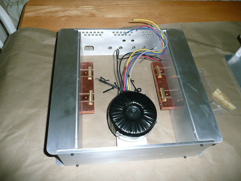
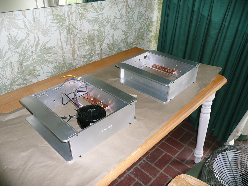
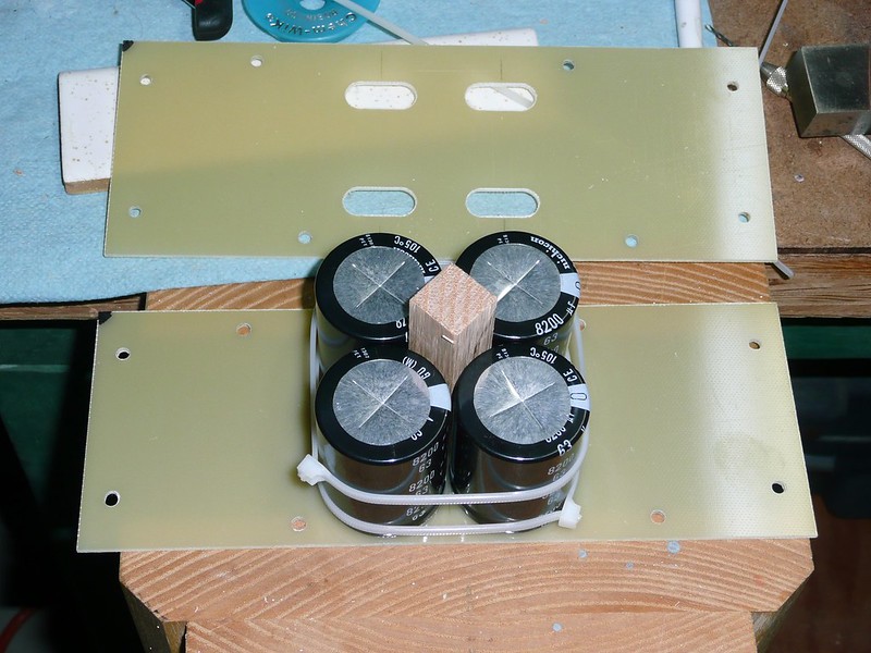
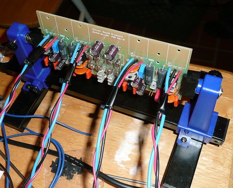
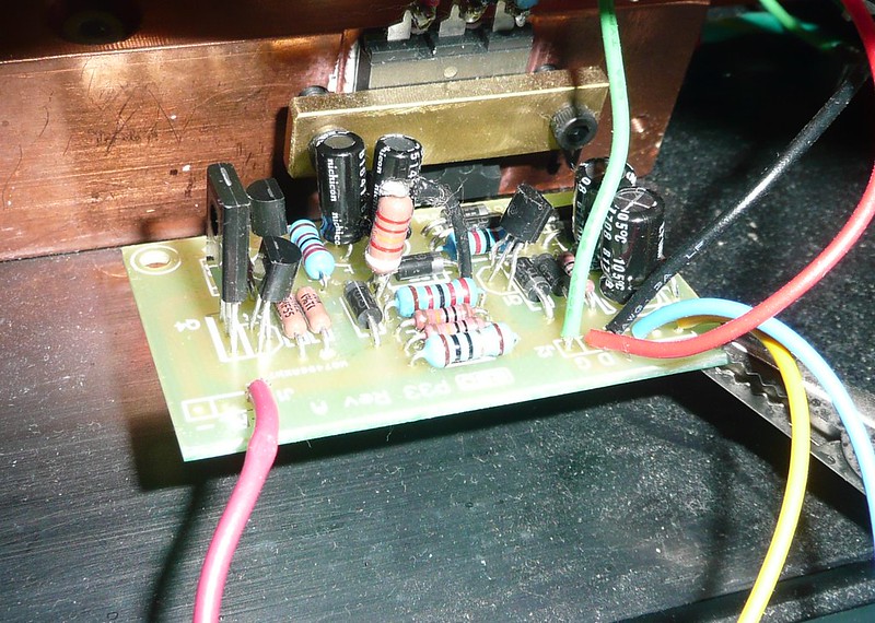
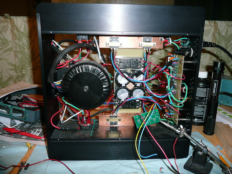
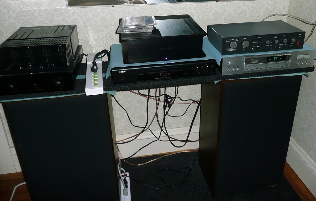
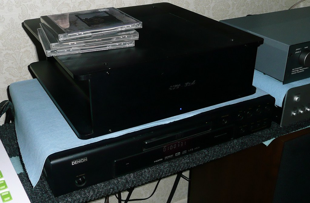
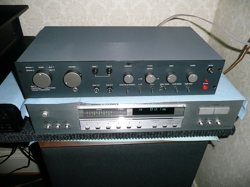
After building a pair of speakers that sounded very good and having reasonably good success restoring vintage audio I was anxious to build my own amplifier from scratch. Rod Elliot’s Elliot Sound Products (ESP) offered an amplifier kit based on a single board. His site gives instructions on how to build the kit for a 60-70 WPC amp. Since I learned most of what I know about audio electronics by reading articles on his site I thought I would give it a try. I bought the board kit (P3A) and his speaker protection kit (P33), then it was up to me to design a case and power supply for it. After several different case ideas based on extruded aluminum and other materials laying around the shop I work at I settled on this design.

40085495503_cf7ee0f073_b.jpg

46998360982_8ba5435e5b_b.jpg

46998361312_bf781c59df_b.jpg

46998361512_07d3033396_b.jpg
 

Attachments

  • ESP-P3A_Amplifier1.JPG
    ESP-P3A_Amplifier1.JPG
    13.8 KB · Views: 35
  • ESP-P3A_Amplifier2.JPG
    ESP-P3A_Amplifier2.JPG
    21.6 KB · Views: 28
  • ESP-P3A_Amplifier3.JPG
    ESP-P3A_Amplifier3.JPG
    17.5 KB · Views: 25
  • ESP-P3A_Amplifier4.JPG
    ESP-P3A_Amplifier4.JPG
    25.3 KB · Views: 28
  • ESP-P3A_Amplifier6.JPG
    ESP-P3A_Amplifier6.JPG
    37.7 KB · Views: 42
  • ESP-P3A_Amplifier7.JPG
    ESP-P3A_Amplifier7.JPG
    35.8 KB · Views: 36
  • ESP-P3A_Amplifier8.JPG
    ESP-P3A_Amplifier8.JPG
    31.4 KB · Views: 40
The P33 protection board - I had a bit of trouble with this and it wasn't the fault of the board. It didn't like the snubber caps around the rectifiers.

33175484378_5f0057bd10_c.jpg
 
In this picture the case has been fully anodized. The output transistors sit on copper bars for maximum heat extraction. The transformer is a Plitron 25-0-25 toroid.
Above and below the filter caps are industrial relay sockets that accommodate a pair of 24V relays.

33175488028_5c3c7529f7_c.jpg
 
Very nice project. I like the case. How do you like the sound? I have parts for the P101 build but no enclosure yet. Unfortunately, I am not as skilled with design so I will have to fork over $$$ for an enclosure.
 
Thanks all for the nice responses!

The sound as far as I can tell rivals my main systems even though I have to account for the fact that the test setup I'm running it in is a very poor acoustical position in my house. Everything I've played in that location has a pronounced bass resonance.

But another pleasant surprise is the pre-amp I picked up for the amplifier. Last fall I got an Apt Holman pre-amp for an attractive price - it's wonderful!

It's a fairly full featured amp and I liked that it has the ability to reverse the phase. I've turned down the base control to compensate for the crazy resonance.

46172661425_9fca0c515f_c.jpg
 
Great work, the case you made looks fantastic, I wish I had such metal working skills. There is something really gratifying about making something yourself.
 
Great work, the case you made looks fantastic, I wish I had such metal working skills. There is something really gratifying about making something yourself.

What's even better is when you're a design engineer. You get come up with cool designs and skilled machinists make the parts for you.

Here is a real big example of that: I'm the guy in the light grey shirt. The automation is my design but a whole bunch of very skilled technicians made it work.

https://www.linkedin.com/feed/update/urn:li:activity:6362256489930981376
 
This looks amazing. The case design is awesome.

I have a question about ground wiring-as I'm contemplating building one as well.
My understanding is that the center tap of the transformer, the chassis, the power line ground, the outside of the RCA jacks, and the ground side of the speaker jacks are all connected.

I just wanted to make sure of this, since getting this wrong would be very bad.
 
OK, where to start?

The transformer has two secondaries (4 leads total not including primaries). Each secondary pair is connected to the AC leads of a bridge rectifier. There are 2 rectifiers, one for each rail polarity (+ or -).
One rectifier output goes to either the positive or negative capacitor lead depending on which side the rectifier it's on. The other rectifier output lead goes to a copper strip ground between the two capacitor banks.
The - (minus or black) speaker lead comes back to the same capacitor grounding strip per Rod's instructions. The grounding strip is then connected directly to the grounding lug of the IEC socket. There is another chassis ground that can be seen in the lower left of the case back in the model image above. This is the 'star' ground, all the grounds from the circuit boards go there. It is also connected to the IEC socket ground. There is no daisy chaining and I hear no hum.

Hope this is clear.


This looks amazing. The case design is awesome.

I have a question about ground wiring-as I'm contemplating building one as well.
My understanding is that the center tap of the transformer, the chassis, the power line ground, the outside of the RCA jacks, and the ground side of the speaker jacks are all connected.

I just wanted to make sure of this, since getting this wrong would be very bad.
 
, the outside of the RCA jacks
If your going to build the same amplifier. Buy the boards from Rod.You will then have access to his build instructions. Almost idiot proof..The RCA input jacks will likely go to a signal ground point on the circuit board. This is isolated/ decoupled from the "star ground" . Or at least it is on my P-101.:thumbsup: Which sounds awesome..
 
Last edited:
Back
Top Bottom