Converting the AD797 MC Phono Pre to a MM Phono Pre - A Mixed Design.

And I finally figured out why my AD797 add on never worked.
I just made the same mistake AGAIN arrrgh! But now I identified it.
Thinking the AD797.asy.txt was a typo...
when I downloaded it, I filed it as AD797.asc! thinking it was
an asc file and not the asy that should go to the library and be used there.

In the mean time I keep getting lost on the board trying to recall which part
goes where and what the callout/ref. should really be. For example from
Hypno Toads AD797 Pre amp; there is no listing for any cap that is 100nf, 10uf,
10nf or 10pf. Yet on wyns schematic there are 32 of them.

There are a lot on the actual board also.

Note: This is not a slam on Wyn, I need to go back to the
the AD797 thread and see what Wyn did.

Wyn, you are more than welcome to share pics of
your actual board, I know that AI would appreciate it.
 
Wyn,

Would you be kind enough to attach your original MMorig in 2 channels please?
Would you also be kind enough to attach your mixedmm 2 channel schematic.

I hope the schematics work for me to isolate them, that is ch1 on a page
and ch2 on a different page to print it out so I can read it and see which
values changed on the board and where.

When every I duplicate a channel and attempt to create a new schmatic from
it in a new schematic, LT Spice changed all the designators.
For example what was once R9 becomes R5.
What was once R44 becomes R9.

Anyway I guess you don't have to, I figured it out I hope.
It will just be slow going for a bit and school kicked in also.
 
And I finally figured out why my AD797 add on never worked.
I just made the same mistake AGAIN arrrgh! But now I identified it.
Thinking the AD797.asy.txt was a typo...
when I downloaded it, I filed it as AD797.asc! thinking it was
an asc file and not the asy that should go to the library and be used there.

In the mean time I keep getting lost on the board trying to recall which part
goes where and what the callout/ref. should really be. For example from
Hypno Toads AD797 Pre amp; there is no listing for any cap that is 100nf, 10uf,
10nf or 10pf. Yet on wyns schematic there are 32 of them.

There are a lot on the actual board also.

Note: This is not a slam on Wyn, I need to go back to the
the AD797 thread and see what Wyn did.

Wyn, you are more than welcome to share pics of
your actual board, I know that AI would appreciate it.
I confess to being somewhat confused as to what you want or what your current issues are.
I could post a picture of one of the assembled boards, but again, I'm not sure what you hope to gain from it.
Hypnotoad's schematic was just a stripped down, basic, version and lacked many of the necessary decoupling caps etc.
I explained the reasons for many of the other caps etc. in this thread and, in all honesty, I don't see the need to repeat.
I'm sorry for your confusion with the .asy files, but I believe that I also explained what to do with the .asy and .asc files earlier.
Is there a specific issue that you need help with?
 
The primary issue it going from a good original circuit schematic to the PCB.
Then a good working schematic with your mixedriaanew.

When ever I tried pring off the BOM from the schematic
they had like 3 times as many parts, etc.

Then I was then going to isolate one schematic only and
place it into a new schematic in LTSpice.

First, I click on the copy/duplicate icon (next to the sissors).
then click and drag to only the lower channel to select that channel of the schematic.
Once selected I move the cursor to the File menu (it drags the schematic along with it).
From the File menu I select the first option, New Schematic.
A new schematic is created with the schematic in the new window.
Use the center mouse scroller to shink the schematic to readable size.

Look at that schematic now. The designators have all changed.
What is R6 in the top schematic and R14 in the bottom schematic,
becomes R5 in the new schematic.

I was hoping this would be simpler to update the parts
to the board but it won't be a simple task.

So from U4 on the actual board There is no R1 around it.
R2 is the closest one but it is listed as 47r on the board.
And R1 on the board is next to device OA3.
Next to U4 in the feedback path is C15 with gainR4-300K and
in R1-18K in series, paralled around C15 a 0.01Uf cap.

So nothing matched up with any of the schematics
and with the board.

With a picture or two at least I could see where on the
board I would need to add the correct parts.

I believe that all the issues are now resolved- please let me know if that is not the case.
 
Wyn - I believe they are also resolved. It's now time to order the remaining parts
and start assembly and test. Things have kicked back into high gear here with
schools, mine and kid, along with everything else.

I check in from time to time with updates etc or things to figure out.

Thank you for your help, thoughtful suggestions, and a bit of guidance about how
to sort though everything. I'll keep y'all informed as I go through
this process--will be asking questions or concerns from time to time.
 
Cap Question,

For the cap that go between the opamps power supply rails, 10uf 50v,
which will have the best effect for the operation of the LME49710s
or other opamps that I'll insert there?

Bi Polar, Low Leakage, Low ESR ?

I know we bypass that with a 0.1uf cap.

Maybe low leakage because we don't want current
leaking through the cap to the other side?
 
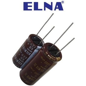
Polar and I used those Elna Silmic II's, make sure you get the polarization right, pos to pos and neg to neg or poof!!
 
Cap Question,

For the cap that go between the opamps power supply rails, 10uf 50v,
which will have the best effect for the operation of the LME49710s
or other opamps that I'll insert there?

Bi Polar, Low Leakage, Low ESR ?

I know we bypass that with a 0.1uf cap.

Maybe low leakage because we don't want current
leaking through the cap to the other side?
Just go with Hypnotoad's recommendations. They seem perfectly fine to me.
 
Okay, Hypnotoad. Thanks for the clarification. With my initial look I didn't see the 10uf 50V cap
on drop down, so I was going to use a Nichicon there, maybe a KZ cap, UKL low leakage
possibly even a ChemiCon as their ripple measured significantly better than other caps
when I used them in other circuits. That surprised me because
it got drummed into my head--"ripple is a circuit function, not a cap function".
My scope didn't lie to me did it? Even if it is an old Tektronix 2246MODA with a
measly 100MHz bandwidth.

I did find the SilmicII 10uf 50V with the larger lead spacing. :)

Thanks gentlemen.

Post Script: Hypno's statement might confound you at first,
"make sure you get the polarization right, pos to pos neg to neg."
until you look on the body of the Silmic II caps--they show no polarity!
At least the ones in my supply don't. They may be a few years old though.
Otherwise the the SHORT lead is - NEG.

I haven't checked yes, Hypno, are there any silkscreen errors on the board
regarding electrolytic polarity on the neg rail? Where NEG goes to Vee
and POS goes to ground?

USMC_Spike
 
Last edited:
Okay, Hypnotoad. Thanks for the clarification. With my initial look I didn't see the 10uf 50V cap
on drop down, so I was going to use a Nichicon there, maybe a KZ cap, UKL low leakage
possibly even a ChemiCon as their ripple measured significantly better than other caps
when I used them in other circuits. That surprised me because
it got drummed into my head--"ripple is a circuit function, not a cap function".
My scope didn't lie to me did it? Even if it is an old Tektronix 2246MODA with a
measly 100MHz bandwidth.

I did find the SilmicII 10uf 50V with the larger lead spacing. :)

Thanks gentlemen.

Post Script: Hypno's statement might confound you at first,
"make sure you get the polarization right, pos to pos neg to neg."
until you look on the body of the Silmic II caps--they show no polarity!
At least the ones in my supply don't. They may be a few years old though.
Otherwise the the SHORT lead is - NEG.

I haven't checked yes, Hypno, are there any silkscreen errors on the board
regarding electrolytic polarity on the neg rail? Where NEG goes to Vee
and POS goes to ground?

USMC_Spike
The board seems to be correct- or at least none of my electrolytics have "blown up" as yet :).
Ripple is a function of the capacitance and to a lesser extent the non-idealities and the frequency content in the voltage/current waveforms. You can add "real" caps in Ltspice or modify a cap model to include things like inductance (from the self resonant frequency spec) and equivalent series resistance. You can also model "soakage" (dielectric absorption) but that's not so easy to do and not especially important for supply decoupling purposes.
 
Post Script: Hypno's statement might confound you at first,
"make sure you get the polarization right, pos to pos neg to neg."
until you look on the body of the Silmic II caps--they show no polarity!
At least the ones in my supply don't.
These have the polarity maked on them:
elna_silmic_350_0.jpg

Do yours look different?
 
At first glance yes, then I went back and checked again just to be sure
and include pics to post here. It must have been my early rise and
getting ready for school at the same time. I just checked now and
thought I must have stroked, or something. At least the once in
the shoebox ALL show polarity as in rothwells elna pic.

That is, at least all the Silmic II caps in their bags in my box
labeled Project Caps, Transistors. As I went through it
I've got about another 10 bags with most with Nichicon PB caps
and one with ChemiCon BP caps.

Naturally, the BP caps don't show polarity,
because Bi-Polar caps don't have polarity.

If I find the mystery bag of caps I'll post a pic.

And as it goes, I always have plenty of caps of the incorrect value/voltage
and/or lead spacing.

Tube amp stuff vice Solid state stuff, ne'er the twain shall meet.
You need twice the inventory for everything.

Time or order more parts, as soon as I identify them all.

Thanks for the heads up.
 
While I'm in a holding pattern for the moment,
I went back through the thread a bit and had some
other questions.

Hey Wyn, somewhere back there you'd mentioned that you
were a "Rodie" for Yes. And since you were over on the other
side of the pond...I was wondering what kind of stuff you did for them.

Why I ask, is in the recent past, there was an interview with Rick Wakeman,
which i never would have guessed by the way he looked now as opposed to
back then.

Rick was talking about electronics and working on some of the old synths...
he mentioned how he said that they were so difficult to work on, etc mainly
he confessed, because that way he could work on them himself and have
his buds send them to him.

Since you are a EE on steroids, I was wondering what you might know of
Ricks' electronic skills and if during your tenure with them, what you might
have shared with R.W. electronics wise?

How was the Yes generally electronically aware? Or were they smart enough
to find people who could keep them out of trouble and keep their gear running
with out blowing up? Or after spills etc?

Since R.W. was a pioneering performer on that, Moog, don't know if it was
a mini-moog or a different one. Were you part of that, then?

Well, my time with Yes was brief. I spent a year in college living in London in a hall of residence just a bit north of Imperial, then once the semester ended I had to find somewhere else to live- which proved to be quite difficult. In any case, I shared digs with a friend who was a bit older than I (I had just turned 18, he was 20) who also was sponsored by Marconi Space and Defense Systems at Imperial and he was into the whole recording/rock "scene" in London. He lived in New Malden- fairly close to the Decca pressing plant in fact (which is why I joined Decca at the plant as a gopher for the summer- they paid me a pittance but it was a very interesting time). In September I joined him with Yes- they were starting the Fragile tour- and I traveled with them to the first concert in Devon, gradually traveled up to Scotland, then back down to Southampton at the end of October when I left and joined my sponsors in Portsmouth (just a tad East of Southampton on the South coast) for the year I had agreed to, before returning to college.
My memories of that time are pretty sparse. If I remember correctly Wakeman had just joined the band so he really wasn't fully integrated at the time we left for Barnstaple and it was only after a few concerts that he stood out. I was involved with setting up the equipment and the "laser show". Actually that was a joke- it was just a light show, but lasers were just starting to appear and the buzz was that it would be really neat to have them in future shows- it was rather prescient in fact (until people started getting blinded...)
So, I had no involvement with Wakeman and I don't remember his gear at all. About all that we did with the band that was interesting was sharing in the passing around of a tequila bottle, salt , and limes as we sat in a circle- there were no drugs involved that I could tell- which is more than I could say for the audiences :).
 
Last edited:
That is good stuff, thank you Wyn.

Moving right along, as I've gone back to the AD797 help desk thread and you had mentioned
other important aspects of the turntables and their cabling; (i.e., inductance, arm resonance, wiring impedance/resistance
etc. this is just recalling from memory)

Since I've not done this before and have a vague idea of the concepts etc. Help would be appreciated.
Please know that I've talked to some of whom I thought were my more knowledgeable profs at my community
college, and the more knowledgeable folks who are honest don't really know. Or when I asked about the Laplace
function etc, they confessed their university studies were the last time they've ever seen that and never
used it in their professional careers,

I even asked some physicists about the vector scalar stuff and the w(omega) radian functions and they
kind of poo pooed the topic, etc.

To get back on topic...Turntable, cartridge, tone arm, cable and other measurements to define
what I actually have.
Well, I've used Laplace functions many times in my jobs over the years, and obviously even since, so it's hardly unusual, but I don't know what it is that you need.
I also don't know what you mean by vector/scalar, and what about it would cause Physicists to poo-poo it. They use the dot product in a number of areas- as do EEs, especially those that are involved in electromagnetism.
 
Last edited:
Since I've not done this before and have a vague idea of the concepts etc...
Is there a chance you're trying to run before you can walk? Many people on the forum have made DIY phonostages from tried-and-trusted designs and been perfectly happy without the need for extreme modelling.
Turntable, cartridge, tone arm, cable and other measurements to define what I actually have.
Modelling is an extremely powerful tool but you have to have accurate models or else the whole thing is is of dubious benefit - or downright useless. Modelling with very simple resistor/capacitor/transistor circuits is easy enough, but creating accurate models for transducers and their real-world behaviour is something else.
Wyn has been doing this kind of stuff for years in a professional environment. You're not going to get anywhere near close to his level of expertise by asking questions on a forum. 40+ years of hard-earned knowledge and experience can't be condensed into a few forum posts and personally I think it's a bit disrespectful to think it could.
Fortunately, you don't need that level of expertise if you just want to make a phonostage from a kit.
 
Is there a chance you're trying to run before you can walk? Many people on the forum have made DIY phonostages from tried-and-trusted designs and been perfectly happy without the need for extreme modelling.

Modelling is an extremely powerful tool but you have to have accurate models or else the whole thing is is of dubious benefit - or downright useless. Modelling with very simple resistor/capacitor/transistor circuits is easy enough, but creating accurate models for transducers and their real-world behaviour is something else.
Wyn has been doing this kind of stuff for years in a professional environment. You're not going to get anywhere near close to his level of expertise by asking questions on a forum. 40+ years of hard-earned knowledge and experience can't be condensed into a few forum posts and personally I think it's a bit disrespectful to think it could.
Fortunately, you don't need that level of expertise if you just want to make a phonostage from a kit.

Not disrespectful I think, just naïve, and we're all that...
I'm actually jealous of his enthusiasm.
 
@rothwellaudio,

Thank you for your comments. I understand and disagree, and yes, I am quite aware of the fact
that I'll never master some of these models and modeling in my lifetime, however that isn't the issue.
Your statement..."personally I think it's a bit disrespectful"...

You are free to personally think what ever you might. It has nothing
to do with reality. While I appreciate most people here because the
collective intelligence of the members and their assistance.
However that doesn't negate the fact that some members
might be better off in the flat-earth society.

AND

Just because I can't, does not mean I cannot inquire does it? Of course not.

This is why I've appreciated all that Wyn has done, not only to give some insight,
but was firm at time when I asked for help, he refused and essentially had me do
the work myself. He assisted with a process in which I derived the answer.

ADDITIONALLY

You are not alone in your belief that because people ask questions and would like
to know answers that they are labeled "difficult" "not a team player" "disrespectful" etc.
Sure I might be trying to run before I can walk, just as we all did as infants, none of us
could stand or walk...it didn't prevent us from trying though did it?

I've succeeded to function at a high level despite attempts to prevent it. At 14 I was selected
by a well known skipper to join his crew for a California Yacht Club Match Race Series.
I was also the only freshman in my high school to earn a varsity letter at 4'4" and 59 lbs.
I also wrestled, surfed, sailed, acted, did technical theatre, track (ran 2 mile) played Lacrosse,
earned leads and best supporting roles in plays Jr. High, High, and College. I was selected to represent
my school in the Key Club (Kiwanis Jr. organization) at the State/National Student Conferences.

After secondary school I joined the Marine Corps, finished 1st in my Boot Camp class, held the range
record at the Machine Gun course, selected for Officers Candidate School where I was the Honor Graduate.
I continued this achievement level throughout college too, Elected by my peers to Command our Fish Drill
Team and Finished 1st in the State of Texas, and placed 3rd Nationally. Also a member of the 2 time National Championship NROTC-PFT team as well as raced in Olympic qualifying events, State and National Championships in Lightnings and Solings. I earned reconition as a pianist/composer as well as received a University
Achievement Award for my work as music director booking our fountain and lounge shows.

When I was teaching, it is important for students to do the assignments, especially those
of student athletes. Imagine my surprise when the administration called me down to their
office and said they changed the grades earned and which I submitted of student athletes
and told me it was for my longevity in the district (that they changed their grades.)
Then they pulled me along until mid year and said they weren't going to certify my teaching.

I wasn't going to have any of these
and I fought the corrupt $1.2 billion dollar district and won. They said that "if we can't get
rid of him then send him over and have him teach ISS (In School Suspension)." They did,
and sent me to the worst, the poorist, highest at risk middle school in the district. I ended
up running their 6th grade program, which for teachers is the most difficult grade to teach.
and I did; the kids ended up really appreciating me. I had some go on to AP Math their
freshman year in high school. Despite their attempts to ruin my career, I have three different
teaching credentials ranging from Career Technical Education (7-12) Business Education (6-12)
and Special Education (EC-12).

When given lemons, I persevered, I made lemonade.

In my current educational endeavors, I'm working on a few associates degrees, Electrical Engineering Technology
and Electrical Engineering manufacturing Technologies, six hours separates the degrees. I would have a 4.0 save for a few shitty profs who don't think their students should do better then they did.

All this with only a few years to go before retirement.

@Wyn,

I'm trying to figure out what I need to do with the turn table to get it ready.
Maybe I assumed that you might help with that as in the AD797 Help desk thread
it seemed there was a lot if data that people weren't considering.
If I was incorrect, then I'll stand corrected.

Of course, I know that you are very familiar with Laplace and other functions and modeling,
I was just trying to get a better handle on it all by asking my professors.
 
Back
Top Bottom