Custom Latino ST-120 Build

sKiZo

Hates received: 92644 43.20°N 85.50°W
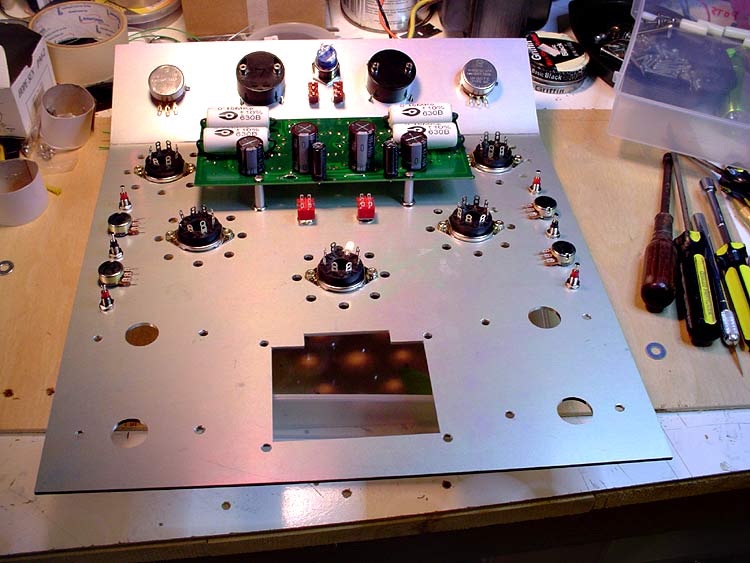
Picked up on a Latino ST-120 tube amp kit a bit back with the intention of having a bit of fun with the build. The Dynaco ST70 clone chassis is quite nice, but ... I planned from the start to go with BIG bottles and needed some more room. This also gives me the opportunity to increase the choke size and hide the quad can cap underneath. Long as I'm at it, how about a custom front panel?

We had a real nice thread going during the selection process that has some good info on requirements and what's available if you're looking. Also has some of the preliminary musings on what I wanted to end up with.

http://www.audiokarma.org/forums/showthread.php?t=511281

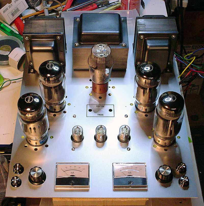
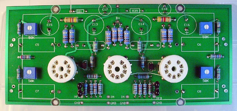
For those not familiar with the amp, here's what the normal build looks like.

VTA120top.jpg


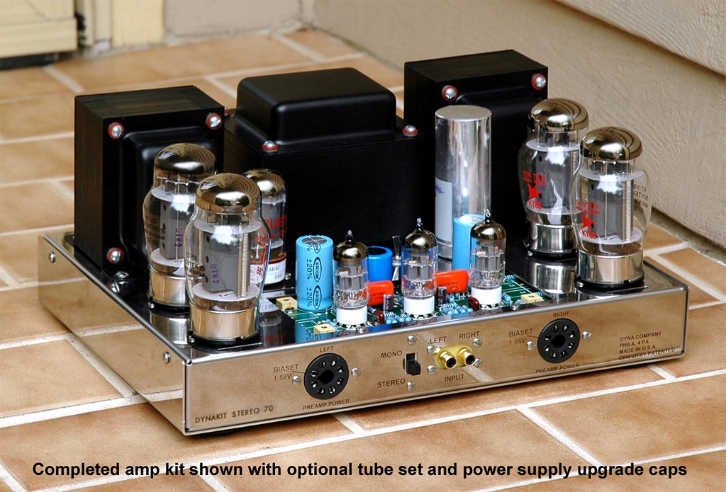
Conservatively rated at 60WPC but run more like 70WPC with no effort. People who have them tend to be quite pleased with them. Quality components, and very concise step by step instructions, and Bob Latino is very strong on support if you manage to solder yourself into a corner. Also very competitively priced.

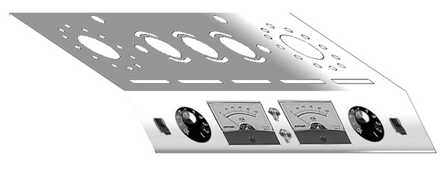
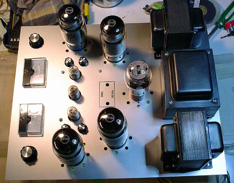
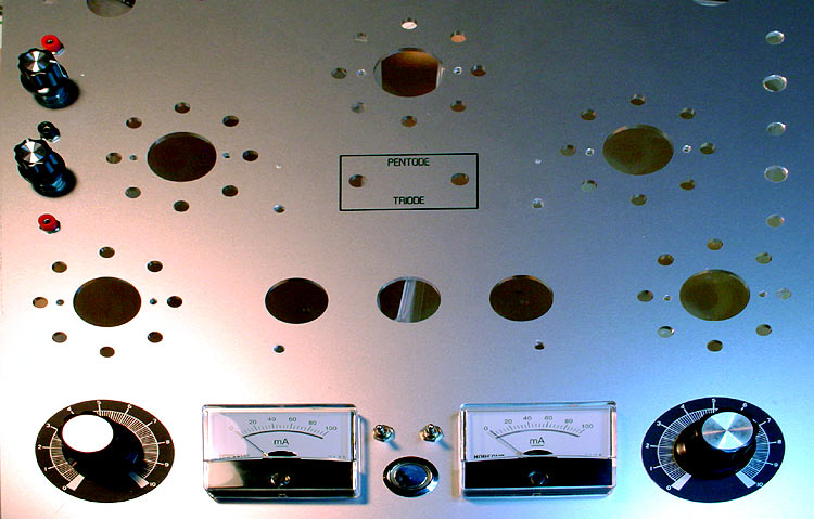
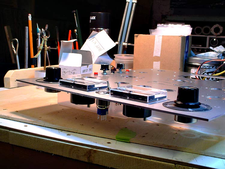
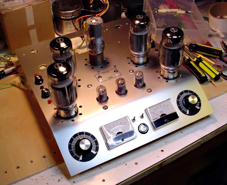
The amp is designed to fit into a standard Dynaco ST-70 chassis with absolutely no modifications. One of my biggest concern was the TungSol KT-120 tubes I plan to use for power. Those are massive compared to an EL-34 or KT-88. I also plan to use a big bottle rectifier instead of the stock GZ-34. I also want bias meters and standard adjustment pots for convenience. And bling of course. <G>

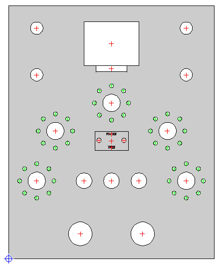
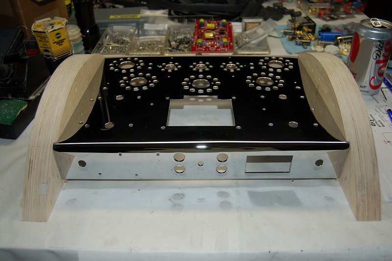
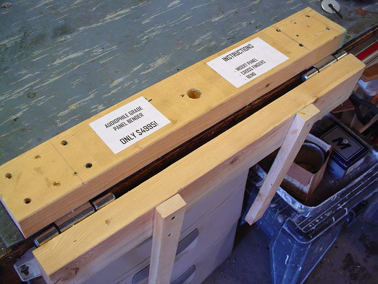
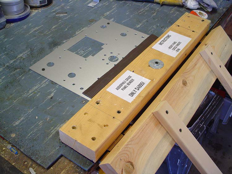
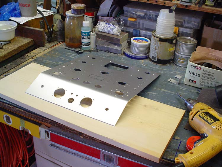
So ... step one. Design a chassis ...
 
Last edited:
Designing the Chassis

Scratched out some preliminary drawings and some kind folk pointed me towards Front Panel Express. They have FREE software for design and get rave reviews for the quality of their work. You design it, send them the output file (knowing immediately exactly the cost), they run the CNC work and ship it back. I doodled around some and came up with this ...

fpe-panel-ordered.jpg


That accounts for all the holes that will have exposed edges. I figured to do all the holes for mounting hardware and such myself. Keeps the cost down some and gives me a fudge factor as I can match those exactly piece by piece during the actual build. The front section of the panel will be bent for the controls and meters. More on that later, but here's an early concept drawing.

FPD14-front-panel-bent.jpg


Very early ... not much resemblance to what I actually ended up with. Ain't that always the way? The panel will drop into a wood base. Designed but not yet built while I check out wood options. That will also have a separate aluminum panel inset into the back for all the connections, including the input RCAs which are moved from the standard front location. Probably just go with good old oak as that's easy to machine and easily available. Only concern there is resonance as that's a hard wood and I expect could pick up a lot of vibration which can be a concern with amps.

OK then ... got the panel back a week later, drilled all the mounting holes (well, most of them anyway) and here's the first dry fit from the top.

chassis-top-fit-01.jpg


Quite happy with it ... definitely different. One of my major concerns was adding space between the bottles, and that worked out right nice. There's even plenty of breathing room between the big bottle rectifier and the transformer.

chassis-top-fit-02.jpg


Excuse the wandering knobs ... the small ones next to the driver tubes in this pic are for the bias pots. Once I got the tubes in, I can see where that would have made for a lot of tender fingers. Just as well to put them on the front panel. Only change there is now the power switch and light will move to the wood front of the chassis. There will also be a couple mini-switches between the meters so I can switch from front to back on each bank when reading or adjusting bias.

Speaking of driver tubes ...
 
Last edited:
VTA Driver Board

As said, the original design had this hanging out the top. My chassis plate was designed to recess the driver board with only the glass of the tubes showing. That required relocating the big caps (C13-C16) to the bottom of the board. That done, the tallest part of the board is the sockets themselves. Here's the finished product ...

vta-board-done.jpg


One nice feature of the board is that both sides have solder tabs so you can flow thru the board and get real solid contact. This was a BIG advantage with swapping the caps to the other side. I just put a temporary riser under each so I got a bit of air space and could also inspect the joints for good flow both sides. Here's what it looks like from the bottom ...

pio-caps.jpg


I also had some fun with the PIO coupling caps, adding a heatshrink cover and custom printed labels to pretty them up. There's always a chance of shorting the standard bare metal cases to ground or worse, so there's actually a practical side to the mod.

Unfortunately, I already had the board built before I decided to replace the original board mount bias adjusters with standard pots. I'll have to pop those pretty PIO's to remove those and add twisted wire long enough to reach the new pots on the front panel. Not a perfect world, and I'm here to keep it that way! <G>

Speaking of not perfect. Somehow or other I missed the target when drilling the mounting holes for the VTA driver board. That put the glass envelopes right up against the back of the holes in the chassis plate. dOH! Easy fix though ... The board is mounted about an inch below the chassis plate and I was able to bend the bolts just a bit to center the tubes. Shhhh ... I won't tell anybody if you don't ...

More later ...
 
Skizo , thank you so much for posting this. I've been struggling on how I should builtd my next tube amp- this is the perfect solution to the whole "panel design" which I've been contemplating.
 
Skizo , thank you so much for posting this. I've been struggling on how I should builtd my next tube amp- this is the perfect solution to the whole "panel design" which I've been contemplating.

Hold the kudos till I find out whether it'll work or not. <G>

Had a few folk tell me I'm gonna end up with stretch marks in the metal or kinks at the bend, but it's no gonna be all that tight or radical. We're only talking about 30 degrees at the most with no sharp corner. I did some research and there's quite a few DIY metal brake designs that should do the job nicely. Something like this ...

diy-sheet-metal-brake.jpg


The panel is only 13" wide, so the hinges will be close enough to keep the wood of the brake from flexing any. I figure to add some air space between the hinged parts and round over the piece that the metal will be bending over. That should make for a nice rolled transition. Screw the panel down tight to the bottom of the brake so it doesn't shift. Keeping my fingers crossed that it'll bend clean, but if for whatever reason I do mar the metal, hey ... nice place for a pinstripe or two, right? <G>

Next step is to dry fit everything underneath the panel - quad cap, chokes, filter caps, etc and drill any additional mounting holes I'll need for that. Once I'm sure everything fits, I'll strip it down and THEN do the bend. I plan to space the hinged pieces a bit further apart and roll the edge of the bottom one for a ... well ... rolled bend and I got some leather that I'll use to protect the surface. Once I get the panel where I want it, I'll start in on the wood case. That way I should be able to match the profile perfectly when I drop the panel into the top of the base.

PS ... if you want to play around, here's a link to the FPE software ...

http://www.frontpanelexpress.com/download/front-panel-designer/index.html

There is a bit of a learning curve, but I managed to turn out my first panel after an hour or so. You can also export to standard cad files if you want to take your design to a local CNC or whatever. I can say FPE does some nice work, and it just got better as they added a bunch of options in their latest upgrade.

Still playing with ideas for the base. I found this one on the web and like the crowned tops of the sides ... adds a nice effect.

st70_29.jpg


Give credit where credit is due ... Guy does some beautiful work.
http://wardsweb.org/audio/ST70/

I'll probably just square off the front and back of the side panels and inset the front and back a bit to make the corners easy, then put it together with pocket screws. I also plan to line the insides of the wood with metal to limit any potential EMI.

Total height of the case should be around five inches. The larger chokes I'll be using will be the main thing to determine the final dimensions. Here's a side by side of the stock chokes and the ones I'll be using.

compare-chokes.jpg


The extra height will also allow me to install the filter caps vertically and free up some space for other stuff, or just allow better air circulation. That'll all get hashed out when I dry fit the inside components, hopefully in the next day or so.

NOTE: The stock chokes supplied with the kit are more than adequate for the ST120, even with the larger tube load. I was going more for additional heat dissipation, as I plan to run it HARD!
 
Last edited:
That's a NOS 1972 Philips 5R4GYS built in Holland. Same factory that did the Amperex Bugle Boys, so I have real high hopes for the sound. Parts Connexion was running a special on them for $40 - they usually go for around $55.

--------------------------------------------------------------------------------------
EDIT >> NOT A GOOD CHOICE FOR THE LARGER LATINO AMPS!
I only got about a month's worth out of the tube. Thought it was just me, but have just recently become aware of three reports of early failure. Strong when new, but get progressively weaker until they won't bias up anymore. I've since bit the bullet on a Mullard GZ37 and nary a problem over the last few months.


Not sayin' don't buy it, but ... just sayin', as they say ...

--------------------------------------------------------------------------------------

Only real difference in the spec is the voltage drop is a lot higher than the usual 5AR4 varieties. I'm told I may lose a couple watts output, but I don't see that as a problem. The KT-120 power tubes have loads of reserve in this amp and I may even come out ahead. Plus, I get the big bottle look and reserve of the GZ-37, at half the price.

Just to be on the safe side, I do plan to run a Weber WZ68 Copper Cap solid state rectifier when I first fire it up and until I verify the build. I've also got a Mullard GZ-34, an Amperex 5AR4, and a Shuguang 5AR4 here, so I'll be able to roll some and take notes. There's also a popular diode mod I'll be doing that helps to protect the rectifier - that tends to be the weak link in these designs.

The TungSol KT-120's are also some real beasts - IF your transformer can handle the load - not a problem here. Reviews are that the bass is exceptionally crisp and strong, the midrange is real sweet, and the highs are detailed yet not shrill. Very comfortable listen across the range ... Who could ask for more? They can do 150 watts in a standard push/pull configuration if the amp is designed around them. Won't get anywhere near that with the ST-120 amp due to design limitations in the amp itself, but ... that's a good thing. Won't be driving them hard at all - at those levels they should have long happy lives and be impervious to anything I can throw at them. Bonus - they're actually cheaper than a premium tube like the ever popular SED Winged C ...

UPDATE: > Still a fanboy of the KT120's. The quad has a LOT of miles on them now, and are still number one in the rotation. Also, no issues with the Mullard GZ-37, and I did manage to find a NOS spare before the big price jump.
 
Last edited:
Happy to be of service ... would you like fries with that? <G>

One thing I forgot to mention earlier. Standard practice is to paint exposed transformers as they mostly come looking like shite from hardened goop left over from the forming process when they stack the plates. Quite a bit of work involved cleaning them beggars ...

Couple tricks ... drywall sanding screen? The 120 grit does a real nice job of removing all traces of the goop. I scraped off the big chunks with a razor blade and the sanding screen did the rest. A good scrubbing with a 3M "00" polishing pad finished them up nice. I also used a scribing tool to indent the spaces between the plates and clean up the lines a bit just for the looks. I left the bell covers on during all the dirty bits of the job to keep the core clean.

That actually gave me a real nice looking finish - The stacks are shiny silver with the black grooves as you'd expect. The bell covers turned out a nice low sheen gun metal gray with a light polishing using the 00 pad. I decided they looked good enough, rather than paint them (trapping heat), I just gave them a couple coats of Never Dull. Stuff is made to work on motorcycle chrome, so I figure the metal is sealed nicely and I shouldn't have any rust issues. If they go dull, easy enough to touch up.

Of course, this is with the Latino transformers - can't say what the results would be with another supplier ... if another brand doesn't polish up as nice, then you've still got a real nice surface prepped for paint.

EDIT: > I was eventually talked out of sticking with the bare metal look and went with Krylon Fusion satin black after a good rubdown with alcohol to clean off the Never Dull. Truth be told, I was already seeing some light brown on the transformer plates a couple weeks after stripping them. dOH!
 
Last edited:
Now what I'd like to do once you get yours all put together and working is to have a nice little show down against my KT120 amp (my scratch and custom design build). Similar output iron, different front end circuitry and different rectification (I used silicon).

But sadly, I'm nowhere near Michigan.

Utah? You're nowhere near anywhere! I have the same problem ... <G>

Seeing your custom Dynaco was what got me going on this though, so thanks, and it's your fault when it blows up!
 
Final Control Layout

Last version looked too busy, so I did a bit more shuffling ...

final-controls.jpg


Seeing as how the holes are drilled, I think I'll stick with it. <G>

The Mallory vernier dials for the volume pots were a junk find. Was digging around for something else, and they popped out. I do like that annular power control in the middle too.

I also went back to having the bias controls at the sides. Plenty of room to get my fingers in there on a hot set without leaving patch marks on the tubes. Also good clearance on the VOM probes when inserted in the test points. One other thing I got to do is cut down the control shafts so the knobs flush out with the top of the chassis plate. Easy enough with a cutoff wheel as long as I'm careful not to heat the metal.

Couple tools I have now designated as "indispensable" for this sort of thing.

special-tools.jpg


The gold thingie is a spring loaded metal punch. Just locate the tip where you want to drill a hole and press down. The internal spring drives the tip into the metal making it easy to locate the bit. Eliminates any walking ... I hate that when that happens.

The blue thingie is a deburring tool. Rather clever little device. The blade swivels in the handle - just insert it into the hole and walk it around the edges to clean them up. The blade automatically stays square to the edge. Depending on how hard and long you work it, you can even put a miter on the edges. Makes short work of aluminum, but it's actually supposed to be made for steel.

Next step is to put in the bend for the front panel. Fingers crossed ...
 
I really like the look and layout of your chassis, keep the pic's coming. :thmbsp:
 
Are you sure you want to bend the top plate? I think it looks fine just the way it is...would make the amp 3 or 4 inches longer. Just hate to see that nice top plate mangled in any way, or show bend stress marks. Hopefully you have a chance to practice on a couple of blanks? I don't think I'd have the guts to do it.
 
Are you sure you want to bend the top plate? I think it looks fine just the way it is...would make the amp 3 or 4 inches longer. Just hate to see that nice top plate mangled in any way, or show bend stress marks. Hopefully you have a chance to practice on a couple of blanks? I don't think I'd have the guts to do it.

I'm sure I want to bend it, and I'm sure I'm stressing over it ... <G>

Then again, won't know till I try it, right? I'll get into the DIY metal brake in the next day or so. One thing that actually may work in my favor ... I got the "anodized/chromated" metal for the plate. Gives it sort of a textured finish that may help hide any defects. I've already got my first scratch (bound to happen) and you can only see it at certain angles. The metal isn't all that thick either at 2.5mm. Plenty strong to hold up the big iron, but thin enough that it's still easy to work. Worse comes to worse and I do manage to mar the metal, backup plan is to add a wooden accent piece that would cover the bend and make the control surface look like a separate panel.

PS ... I figure bending the plate will only shorten the case about 1½ inches. We're only talking around 30 degrees here ... and if I do screw it up, call it a learning process. I do have some extra 3003 aluminum (same thickness) that I can practice on.

Awesome build so far!
Will the bias meters sit flush with the metal cabinet?

What you see is what I'll get ... the meters do sit around ¼ inch proud of the chassis plate by design. I did have the option of back mounting them, but I think this is a cleaner look and a whole lot easier too. If nothing else, it adds some interesting shadow lines for effect.

meters-sideview.jpg


I plan to use some 3M body molding tape around the edges to seat the meters and eliminate any chance of vibration. Pic also does a nice job of illustrating why I want to cut down the shafts on the bias pots ... dremel tool will make short work of that.
 
Got the bending brake made ...

panel-bender01.jpg


Here's the panel jigged up and already bent.

panel-bender02.jpg


I screwed it down to the bench in a couple places to keep it from walking, and also added a bolt down the center of the brake thru one of the driver tube holes to keep it firm. Metal bent a lot harder than I expected, but ...

panel-bender03.jpg


Like I said, not much of a bend. Here it is after a final fit.

chassis-top-final-fit.jpg


... and from the bottom.

chassis-bottom-final-fit.jpg


I did rework the mounting system for the VTA driver board. Found some real nice threaded spacers and used crown washers on both sides of the plate for a good grip. I also enlarged the holes so I could slide the board around a bit to center the tubes in the holes. Works a whole lot better now.

Enough for now ... next step ... the case ...
 
Last edited:
Back
Top Bottom