Fisher 600-T Restorations

fred soop

Super Member
With a few scheduled events out of the way, it's now time to start this thread. Actual analysis and rebuild notes will be covered later. This will start with history leading up to the project. There are 2 different units involved. The first rebuild has been nearly completed and will be described after the fact. Photos and schematics will eventually appear.


Note on Photos

Photos are linked from Flickr. Original versions are 2218 x 1712 and the versions shown here may be smaller if they still illustrate the point. At this writing, it appears that the serial number, 43453K, can be entered in the Flickr search box as a unique identifier. However, Yahoo seems to be "fixing" things that used to work and the Flickr search will sometimes not find tags or titles for recent images, nor will it find user names. The photostream is located at:

http://www.flickr.com/photos/35089121@N07/with/12421335293/

which may eventually contain non audio related photos, but various sized images can be accessed from there. Relevant photos will have the serial numbers (43453K and later, 38215G) as a keyword.


12417490473_95b70ed76f_h.jpg


12417486213_b9f33ac78e_o.jpg


History

My first system that could be considered "high fidelity" consisted of a Knight Kit KG-870 integrated amplifier, a Knight KN-990 record changer with Empire 880 cartridge, and home built speaker systems consisting of a 12 inch Allied full range speaker with whizzer cone (can't find a photo), eventually upgraded with Electro Voice HF-1 step up kits consisting of a 3500 Hz crossover and TW-35 horn tweeter. The MF-1 midrange kit was never added. A Knight Kit KG-765 AM-FM tuner was eventually added. Don't be misled by that 70 watt rating. The tuner capture ratio was almost in double digits. The record changer was able to track most records at 3 grams after the wires coming out the bottom of the arm at the pivot were carefully adjusted.


12703166764_0986872143_z.jpg


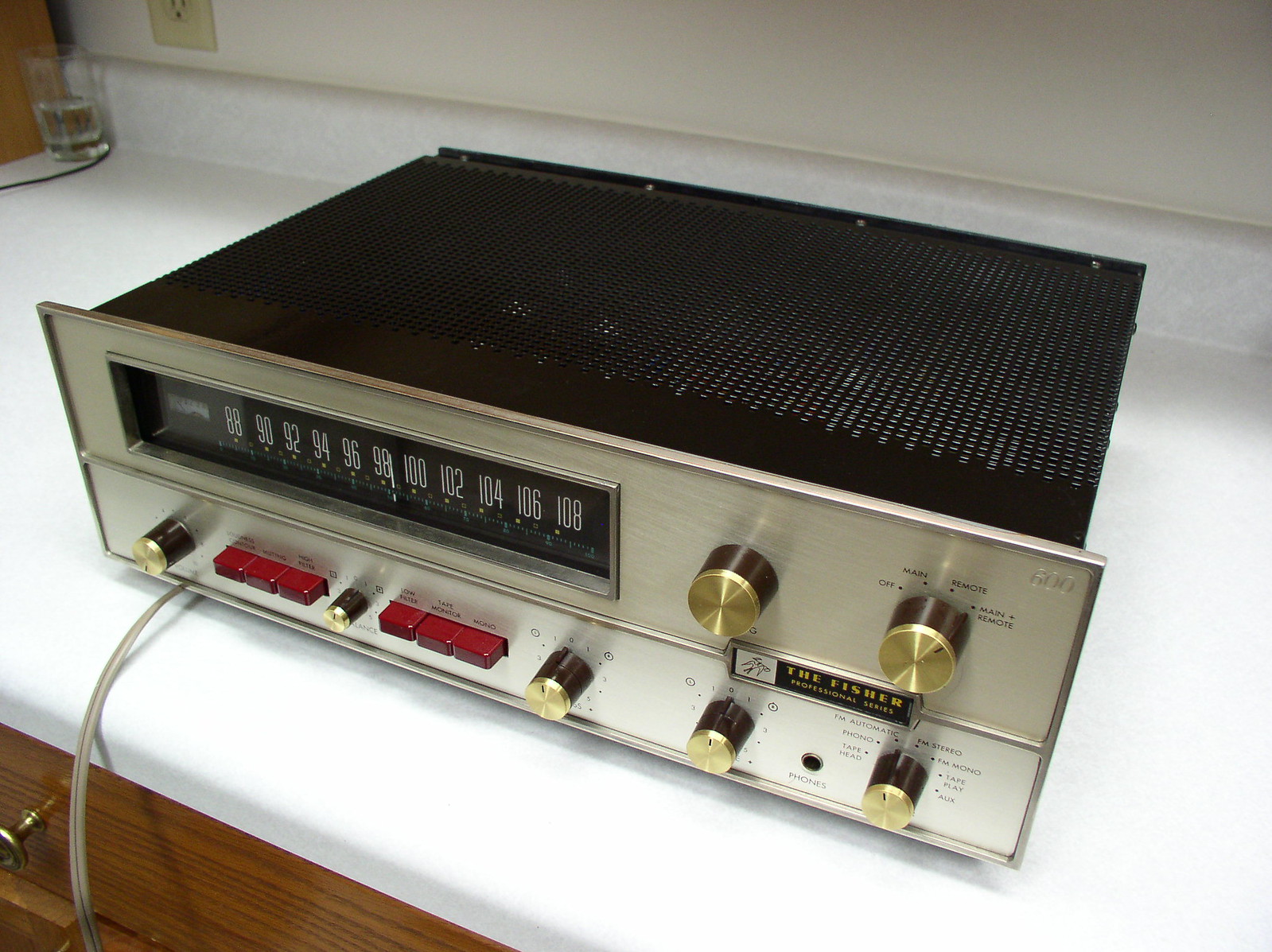
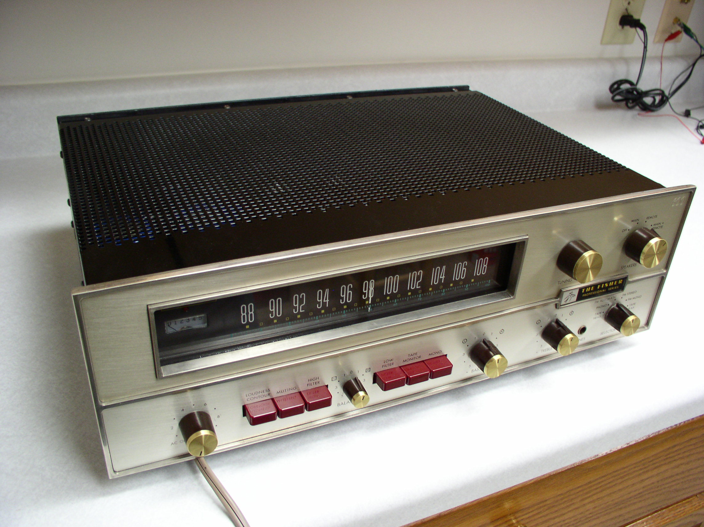
Later, a friend purchased a system that included a Fisher 600-T receiver. It was assumed that the speaker systems, being home built, were probably the weak link. Combining equipment and cross connecting in various configurations quickly demonstrated that the speaker systems were fine and it was the Knight amplifier that was poor. That was a very early transistor design that used automotive style lamps as emitter resistors that would rise in value as more current was drawn. Looking back, that thing probably had 20% crossover distortion.


next: Fisher 600-T Selection
 
I'm looking forward to reading more as I have a (working) 600-T. Did you clean that faceplate, or was it just exceptionally cared for? That is a very nice looking 600-T! :thmbsp:
 
Sweet looking 600-T. I need to get one eventually to go between my 550-T and 700-T. Then fill out the ranks with a 500-T.
 
Wow, very nice 600-T you have there Fred.

Looking forward to this restoration also.

The Photos you have up on Flickr and the details shown in the pictures look awesome, can't await to read the details.
 
I'm looking forward to reading more as I have a (working) 600-T. Did you clean that faceplate, or was it just exceptionally cared for? That is a very nice looking 600-T! :thmbsp:

The faceplate was in reasonably good condition but I did wire brush some of the rims. The top edge near the right has missing plating that was missing when the unit was new. Probably could have gotten a replacement from Fisher. The unit you are looking at is the eBay unit but with my original faceplate. Details will be explained eventually.

Metal cages and transformer covers have been repainted. Knobs are from the eBay unit but I may have discovered a way to clean the old dingy knob caps.
 
Fisher 600-T Selection

In 1966, I was looking at receivers at several locations including Stereoland in Detroit. They had the 600-T and the newly released 700-T. Without having service manuals or published schematics, I had limited knowledge of what was inside these boxes but I was able to determine that the 700-T had a solid state FM front end, compared to the 600-T tube/Nuvistor front end, but the number of IF amplifier stages had been reduced from 5 to 4. I was also put off by the wood grain contact paper on the front panel of the 700-T and the somewhat simpler, cheaper looking metal cages. More recently, I have become aware of what I consider a fatal flaw with the 700-T power amplifier design that will be described later.

I purchased 600-T, s/n 38215G.

The 600-T was probably the most complex transistorized consumer device produced to date. It was largely experimental and Fisher spared no expense in producing it. There were 5 variations in the design in 1965, but 38215G must have been old stock because that is from the 3rd variation. These design variations were mostly changes to the fragile power amplifier section, which was from an early 1960s RCA Transistor Manual. This design was also used in the Heathkit AA-21 amplifier and
probably many others of that era.

There has been discussion about the controls behind the Fisher logo. Those hidden controls existed on the first 4 variations and were eliminated starting with s/n 41001. The controls were not anything critical. One was for adjustment of the brightness of the lamp behind the tuning meter. The other was to set the FM muting level and was redundant with one of the trimpots on the IF board.

The Fisher 600-T served well and the system eventually included a Garrard Lab-80 turntable and Fisher XP-9 speaker systems.


next: Heathkit AR-15 Replacement
 
Received a PM today from someone that didn't want to hijack the thread. Not a problem. Go ahead and comment in the thread so we can all benefit.
 
Okay, it was me, so here's what I wrote.

Questions:

1. You mentioned "a fatal flaw with the 700-T power amplifier design" - could you elaborate, please? I'm about to start rebuilding a 700-T so this could potentially be very helpful to me.

2. I noticed you converted your 600-T's Stereo Beacon lamp to LED, and your dropping and shunt resistors correspond with what I had attempted on my 4400. Does your LED take a while to go dim when you tune off station, or is it as responsive as the incandescent lamp was? On my 4400, the LED remains lit, then slowly fades out as I tune off station. The process from full brilliance to going out takes a full second. Just curious...

Thanks in advance for any assistance, I sincerely appreciate it.
 
This will be a great thread!

If I may, I would like to make a very passionate plea...ok, I'm begging...to PLEASE post the accompanying photos here on AK. That's the only way they'll still be here along with the text a few years from now.

Otherwise, all future members will see is that little empty box where the pics used to be.
 
The problem with posting the photos within AK is limited storage. I'm over 40 photos
for 43453K and there will be at least that many for 38215G. The photos run
600-700K of storage.

As I replied to Ron, the next installment will discuss the "fatal flaw".

Heathkit Replacement

In 1970, always looking for better "numbers", the Heathkit AR-15 receiver
seemed to be better than the Fisher in all areas. One could also purchase
Heathkit (and Knight Kit) manuals separate from the equipment for
evaluation of the design. The 600-T was replaced with the AR-15 and the
600-T was given to my parents. It was located on an end table in the
living room and eventually covered with a lamp, magazines, and newspapers.
As many of you know, the 600-T was temperature sensitive being an all
germanium transistor power amplifier. The bias network alone dissipates
approximately 12 watts and the driver stage is a single ended class A
amplifier with additional heat. So, it overheated and blew up. The output
transistors were house numbered, selected for beta, 2N2147 or 2N2148
transistors, still readily available, so the unit was repaired. It blew
up at least once again and around 1974, the power amp section was stripped
out and replaced with the next generation RCA Transistor Manual circuit
using 40406 through 40411 transistors, though the 2N3055 was used rather
than the 40411. This was an all silicon design and was the best that
could be done at the time.

Power amplifier circuit boards from 1974 rebuild. Note the date code on the caps. 7217.

13319162923_a215497e20_k.jpg


700-T Fatal Flaw

I have recently learned that the Fisher 700-T has the same fatal flaw as
the Heathkit AR-15. That is, the power amplifier is powered with a single
power supply, the point between the output transistors floats at
approximately half the supply voltage, and the amplifier is coupled to
the speaker through a large electrolytic capacitor. I've never listened
to a 700-T but the AR-15 goes "WHOOOMP" when first turned on and a lesser
"whooomp" when turned off. That's the capacitor charging and discharging
and the current path is through the speaker. The woofer cone visibly
moves violently for several seconds. The 700-T circuit, while not
identical, is quite similar to the AR-15 and the AR-15 circuit was
entered into a Java simulator with results shown below.

With an 8 Ω load, there is over 5 volts to the speaker at turn on. This
goes to -226 mV at 0.5 seconds, oscillates back to +335 mV at 3 seconds,
back to -94 mV at 10 seconds, +26 mV at 17 seconds, and finally remains
below a reasonable 10 mV after 24 seconds. If a large low frequency signal
is applied to the input, there is an initial DC offset of approximately 2
volts and it never drops below 100 mV. When that signal is removed, there
is a 25 mV offset for a time. Three seconds after power is shut off, there
is -141 mV across the load. The third trace below is the same as the
second except after the 5 volt spike passes, the vertical scale can be
expanded.


ar15 1401
12703269064_6428be218a_b.jpg


This cannot be redesigned to eliminate that capacitor because the power
transformer has no center tap.

Douglas Self discusses distortion in electrolytic capacitors and capacitor
size of electrolytics needs to be much larger than would be required
simply for low frequency cutoff. He starts with a 47 μf capacitor feeding
a 1K resistor. This circuit has a -3 dB point of 3.38 Hz. At 20 Hz, THD is
0.008%. The capacitor is increased several times with distortion
measurements being reduced and has to be raised to 1000 μf to reduce
distortion to the noise floor. Using similar calculations for the output
coupling capacitor to an 8 ohm load, a capacitor of 100,000 μf would be
necessary, or quite a bit more than the 4000 μf presently installed. YMMV,
but for me, any capacitor coupled output that cannot be modified
disqualifies that model for upgrading and restoration.

I'm guessing that the capacitor coupled design may have been necessary due to the poor reliability of transistor output stages at that time.

next: A bit about my history and qualifications
----------------------------------------------------
 
Last edited:
To answer Rons other question, regarding the LED replacement for the stereo beacon, I rechecked today and there is no noticeable delay. First, in FM AUTO mode, the LED is controlled by Q404 on the Multiplex board. That transistor turns off just as fast as it ever did, whether driving a lamp or LED. The only difference would be in FM STEREO, where the lamp current is used to set a muting voltage for a later stage and there is an electrolytic capacitor involved. I can't see any excess delay there either.

In answering Rons question, I discovered some errors in the schematics. Some of you have been "reading ahead" on Flickr, so page 8 of the schematic has changed. I had left out the section of the selector switch that connects the mono muting in FM STEREO mode. Schematics will be posted here when we get into the circuitry.
 
My 700 "thumps" slightly (as do all my cap coupled receivers being directly connected to the speakers) at startup, but not at shutdown. I put new main and output couplers in it last month, and reduced the "thump" by at least 80%. In addition to the 2A fuses for the amps, I installed 2a fuses between the cap and the speaker jacks. I

If I'm reading the schematics right, the 550-T has the same setup as the 700-T. As would the 500-T

I would think a relay with a time delay in the spkr circuit (3-5 seconds) on startup and an immediate cutoff on shut down would help (aka protection circuit). OR just get in the habit of shutting off the spkrs before shutting down, and waiting 5 seconds before turning on the spkrs. (I've gotten in the habit option 2)
 
Last edited:
Fred - thank you; you've given me an idea to try re: the slow stereo beacon fade out. I didn't replace any electrolytic caps in my 4400's MPX board. If I'm not mistaken, the 4400 MPX board is the same as the MPX board in the 440-T. The 440-T uses a 2N2924 to turn the lamp on and off, and has a 1 uF cap between collector and base. Perhaps that 1 uF is slowly dying? Anyway, I'll check it out soon.
 
Ron, I did have a problem on one of the 600-Ts with the equivalent of C411 on the 440-T. A NEW tantalum was shorted and the stereo beacon was always on as a result. That, along with a few other experiences, .... no more tantalums.

However, I also see C10 and C11, 100 μf, on both sides of the stereo beacon. I'd consider removing C11. With a stereo signal, Q404 is biased ON and discharges C11 to turn on the lamp. Time delay aside, shorting a 100 μf cap with a small signal transistor to turn on the stereo beacon can't be good. When Q404 turns OFF (no stereo signal), C11 is still at 0 volts and now charges through the lamp, eventually turning the lamp off when the voltage rises to the same as the hot side of the lamp.

With the original lamp, calculating current through R37, the lamp draws 36 mA. With your replacement LED, the current would be lower, but, not knowing your resistance values, I can't calculate it. If C11 is not removed, it should either be replaced with a smaller value or a resistor should be added in parallel with the LED (and its series resistor if present) to increase total current draw to 36 mA.

If you have a schematic of your specific unit with the LED changes, I'll look at it.

The 600-T has no equivalent to C11 in a nearly identical circuit except when in the FM STEREO position (muting mono signals). The 700-T has a capacitor in the C11 position but it is isolated from the rest of the stereo beacon circuit by a 47K resistor, so is effectively not there either.

I can't find a schematic for your 4400, so can't speak specific to that model. My comments above apply to the 440-T.
 
More on the 700-T and 500-T capacitor coupled power amplifiers .....

I did some quick changes to values in the AR-15 simulation. The AR-15 main filter capacitor is 8000 μf and the speaker coupling capacitor is 4000 μf. The supply is 72 volts.

Changing those values, but not changing the entire circuit, the 700-T main filter capacitor is 2500 μf and the speaker coupling capacitor is 1200 μf. The supply voltage is 63 volts. The 500-T is the same but with a slightly lower supply voltage.

With the smaller capacitors and lower voltages, the problem is not as severe. But the distortion from the smaller coupling capacitor will be much greater. Phase shift is also an issue but I haven't studied that. The initial surge is reduced to 4.66 V, dropping to -62.7 mV at 400 mSec, +80.8 mV at 3.4 seconds, -22.96 mV at 10.8 seconds, remaining below 10 mV after 13 seconds. Artifacts when applying or removing a large signal are much less. But, with a load of 8 ohms, the -3 dB point is 16.6 Hz and the signal is close to -2.5 dB at 20 Hz. With a 4 ohm load, the -3 dB point is up to 33 Hz.

I actually simulate low frequencies at 19 Hz rather than 20 Hz when modeling the power supply as part of the simulated circuit. This is so the signal will not hold the same phase relationship with the ripple, which might mask problems at maximum signal.

Of course, simulation is only an approximation but it still provides valuable information.

A speaker relay would help at turn off but turn on is still a problem. Delaying speaker turn on leaves the capacitor with only the headphone resistors as a charging path, so the necessary delay would be quite long. This could be fixed by connecting a dummy load when the relay is deenergized. Since this condition would be for a short time and would probably be at idle conditions, the resistor would not have to be extremely high wattage.
 
Last edited:
Fred, I'll get some info to you in a day or two. Thanks!

I did a bit of homework here on AK before I started rebuilding these Fishers, and heeded the warnings of Larry Derouin regarding tantalums...and I do not use any as a result.
 
Another side trip, then we'll get to the actual rebuild .....

My History and Qualifications

I have an electrical engineering degree and first worked in a TV repair shop part time in 1967 (oh, the stories at that place), later interning at Collins Radio (most organized, highest quality company of my career). My first full time position was in the telephone industry (GTE), followed by mainframe computers, performing production test and design simulation (Sperry-Univac, Unisys, and the iterations between them), several short term assignments, and finally, testing cell phone call performance firmware (Motorola).

On the side, I have been studying amplifier design for well over 50 years, but I'm more on the transistor side. With the internet, I've learned more in the last 5 years than the previous 50 and most recently have been digging through the amplifier design books by Douglas Self and Bob Cordell.

My only high fidelity tube unit was a home built stereo power amplifier using 6L6GC output tubes. Actually, there were several of these but each required cannibalizing the previous unit for the tubes and iron.

I did interview with Heathkit in 1970. They were looking for design of test equipment and quickly determined that I was a better fit for audio, so they set up an impromptu interview with that department but there were no positions available at that time.

Story from GTE: Cable for projects was estimated from switchroom floor plans, then extra was added so as to not come up short. So, there were always cable scraps available, sometimes up to 50 feet or more. This was multi color #22 wire and was excellent for stripping out of the cable and using for various projects. (You can see some on the 1970s power amplifier boards, above.) My other time / money sink is model railroading. By the time I left GTE in 1977, I had accumulated a "lifetime" supply of small gauge wire. Fast forward to mid 1990s and yet another model railroad project, and I told a friend that I was going to die soon. He asked why? I said, "I had a lifetime supply of wire and it has almost run out." He said, "You may be onto something there, because when someone dies and you clean out the house, you never find much leftover wire."


next: Fast Forward to 2005 and return of the 600-T
 
So, there were always cable scraps available, sometimes up to 50 feet or more.

Fred, that statement brings a smile to my face, :) for 30 years I worked in the Teleco industry and back when I was working CO install's we also had cable reel remnants left. We had great time splitting up lot's of 4/0 cable for scrap, always a nice bonus $$$ at the end of a large job selling the left over copper.

I still have a box or two of wax string, tie wraps, jumper wire left so I guess I still have a few more years left :)

Do you remember the GTE lenkurt magazine? I always enjoyed reading those and still have many in storage.

Great thread.
 
Last edited:
Back
Top Bottom