Fisher X 100 3 output transformer recommendation

rufleruf

Poor Impulse Control
I bought a pretty nice X 100 3 with a bad output transformer (silly rabbit). I am pretty sure no one is going to respond to my BT post looking for one - so... what would you guys do? I would prefer to only replace the one with something that looks pretty similar to the remaining good one, but maybe this is wishful thinking? I'm not overly reluctant to replace both - especially if there can be some improvement - though I aware these amps are highly regarded in stock form.

I have never shopped for output transformers, so pardon my ignorance. It looks like several sites have Push-Pull transformers listed for EL84 based amps, but I'm not sure if there are some other parameters I need to match. Volts, impedance, frequency response? I see Stancor touted as being very good and members of this forum have recommended them for other Fishers with bad OT's, so maybe one of you knows which one of their products I should use? And of course there are usually quite a few reasonably priced console pull stereo EL84 based amplifiers to choose from on the bay, - some even have similar looking OT's, but how do I know the transformers will work for me?

How do I know it's bad? Bringing the unit up on a variac I get a steady hum out of the left speaker regardless of other settings. If the speakers are on - I have a hum - it sounds like AC. I read a thread about a 500C that had similar symptoms and the OT was the culprit. I'm open to doing more tests of course.

Oh, and the amp is totally stock with a complement of tubes that all test and are known to be good.

Thanks!
Matt
 
. . . Oh, and the amp is totally stock with a complement of tubes that all test and are known to be good.

Thanks!
Matt

How totally stock? These deserve at least a basic refresh. I don't normally condemn an OPT based merely on hum. There are many avenues for AC to weep into a channel. Throwing parts at it based on an anecdotal thread can prove painfully expensive.

If you don't have the bench equipment for full signal path diagnostics, try swapping the suspect items across channels.

FWIW, if that's the problem and you can't find an OE replacement, you may be better off with two complementing OPTs. I have never had a single re-wound or aftermarket OPT sound exactly the same as the original. A good shop will get it close, however. Depends on how anal you want to get about it and how golden are your ears.

Good luck with it.
 
I would at least disconnect the OPT's (do both) from the unit and ohm out the sections. If they fairly well match, with regard to the results, then the transformer is usually good. They either work or they dont'. Getting a hum out of it indicates that it's probably good, and the cause is something else. Is the hum a 60Hz or a 120Hz. Listen to a test tone and then compare the hum on the unit with the test tone.

120Hz is usually in the power supply.
60Hz is elsewhere in the unit.

Listen and let us know what you've got.
 
I plan on doing a rebuild. May get all of it done tonight if I have the caps on hand. I wanted to see if I could get it working before I replaced everything.

I don't know if it's practical to swap output transformers across channels, but I suppose there's probably a creative way to only move a few leads to effectively swap them.

I was basing my diagnosis last night on this thread and following Dave's advice (but trying to translate it to this different amp): http://audiokarma.org/forums/index....loud-left-channel-buzz-hum-im-stumped.702111/

As far as rewinding goes, that is a good thought about matching. Not sure I'd hear it, but hate to find out the hard way.
 
Finish your rebuild and then revisit this.

You may be surprised if the hum is gone with everything else working correctly again.
 
Larry - I just listened to 60hz and 120hz test tones on youtube. I must have a bad memory for tones... I can't tell - but it was def one of the two.

I'll have a listen again tonight and post the result. I'll be replacing the filter caps etc, so maybe I should just do this before I disconnect the OPT's as it's probably about the same amount of work and may cure it.

sgmlaw - that is now the plan.

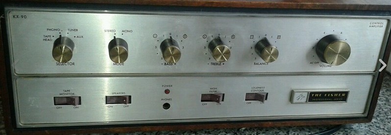
An aside: anyone have the correct manual for this? The X 100 3 linked manual I got off fisherconsoles shows a different beast on the cover and officially shows model X-44 / KX90 with X 100 3 penciled in - mine has 500C type switches, the manual has TX type rocker switches. Maybe they're the same from a circuit perspective?

Mine is like the top one, manual shows the bottom one


Matt: The KX-90 is from '65 and up. The X-100-C would have the Rockers also.

The X-100-3 should be around '62-63. Check the EIA codes on the transformers. Also the can caps should also have a EIA code on them.

Apparently thee were more different versions of the X-100 than Carter had liver pills. And I thought deciphering the 800-C with the Executives against standalones was a PITA.

EDIT: I think I found your unit. X-100-A/X-100-3. No picture on the Front but I have a sneay suspicion.
PM me your email and I'll get it out to you.

Larry
 
made by (1005)Quality transformer and Coil Co. Chicago, Illinois, Last week of 1965 (552).

On this schematic(x-100a/X100-3) the part # for the POWER Transformer is T-1109-C115.
Multivoltage unit(x-100-A only) should have TY1255-c115 This is same for KX-90 manual also.

Output's are shown as T1109-114-1 and 114-2. Same for Kx-90 manual

Then if your # is an OUTPUT TRANSFORMER Check the above power transformer #. If that matches the single voltage # you're good to go with the manual I sent you. The "B" at the end is superfluous.
 
Okay - pretty sure it's a 120hz hum.

Replaced the 2x .022uf, 2x .033uf, 4x .047uf and 1x .01 mylar caps and the two diodes - nothing changed.

Maybe a good sign, the hum comes out of the headphone jack when the speakers are off. Twice while checking and testing the hum went away and was replaced by crackling. Crackling got louder as I turned up the voltage - only got to about 50% before I lost my nerve.

And the output transformer I thought was bad is definitely warmer to the touch than the other.

Can caps? I don't have any electrolytics I can sneak under the chassis in the values needed, so I guess it's time for a parts order. Odd combos:

C1:
100uf 250V
C2:
A-100uf 250V
B-40uf 400V
C-20uf 350V
D-20uf 350V
C3:
A-20uf 250V
B-200uf 70V

C1 and C2A are filter caps if I read schematic correctly?
 
Last edited:
Matt -- If you're hearing 120 Hz hum with the output tubes INSTALLED and operating, then the great odds are that the power supply filter caps are compromised -- particularly the section feeding the screen grids (likely C2B). On the other hand, if you are hearing 120 Hz hum WITHOUT the output tubes installed, that is when the output transformer itself comes into question. Keeping my fingers crossed!

Dave
 
Could also be seriously unbalanced output tubes. If you can monitor current through the tubes individually, maybe do that to see if they come up reasonably close, or honestly just showing some current flow through them all. Check the plate and screen voltages too, no plate voltage would indicate a dead output transformer. I'd also expect that tube to be roasted since it would try to use the screen as a plate, and that wouldn't survive at all. No screen supply would just shut the tube off, and you'd have the hum problem.
 
c1 & c2A are the voltage Doubler Cap's. C1a is the Black Cardboard tube covered cap sitting on the phenolic insulator. VERY IMPORTANT that the insulator stays intact or a new one installed with the new cap (c1) as it's isolated from chassis ground, and has about 200V on the case.
 
Verified: it's definitely a 120 Hz hum. Removing power tubes makes no difference - hum through headphones and when speakers switched on left speaker.

Pulled the rest of the tubes - hum unchanged.

Am I back to post 1? Time to pull the output transformer in question and ohm it out?

Re: Trancendar - How do I determine what to order?
 
Last edited:
A 120hz hum is post-rectifier.

In an abundance of caution, you should also confirm that the other OPT is good. Running a simple test tone through that channel will suffice. Otherwise, you have the possibility that this is a combination of a power supply fault and a dead RIGHT OPT.

Also double check that the left feedback loop is fully isolated from ground per the schematic.
 
Huh - I hadn't thought about the right transformer. I got nothing on either channel trying to play music from my phone. Would be ironic if it was the rt that was bad. I guess it's time to check voltages.

Is there a good explanation somewhere of or Fisher power supply circuits work? I feel like I kind-of know, but it would be nice to really know...
 
The supplies on these are not all that different from others of its era.

These are simple unregulated supplies (explaining the historical complaints about high supply voltages on today's line values). Rectification and filters follow in 3-4 or more stages. In yours, solid state rectifiers were used.

Fisher (and other manufacturers) employed a voltage doubler setup in yours and in many other of its amp designs by in part stacking the first stage filters in series. Imagine stacking C or D batteries to increase voltage as a rough analogy. It allowed filters with lower voltage ratings to be used and a lower voltage (and more robust) secondary winding for the core size.

The first stage of the supply typically feeds the outputs. Succeeding stages off of that supply branch receive additional filtering for more ripple-sensitive circuits. The final supply stage in an integrated amp or receiver often feeds the tape loop/phono stage.

Other supply branches in other models are mapped similarly to supply tuner circuits (sometimes by tapping off the doubler branch) or to supply dc for some small signal heaters and bias supply for outputs.

The rule of thumb for good and balanced supply design is that the rectifier 'sees' the first filter of the supply, and the supplied circuit load 'sees' the last one. That is why loading up excessive capacitance in the first stage becomes a problem with some rectifier types (particularly tubes). The filtration should be tailored to the anticipated load and the ability of the mains switching, transformer and rectification to supply it, and not some hypothetical ideal of zero ripple without regard to the components involved.
 
a real quick sanity check on the output transformer is to simply measure from plate to plate on that channel. If it reads something, and ideally close to what the other channel reads, chances are fair that it is fine. Final check would be from the center tap (red wire) to each plate to confirm that it reads about half of what you get plate to plate. I'd do that before digging too deep into possible power supply issues.
 
Back
Top Bottom