

neevo
Super Member
I’m a competent desolderer and solderer. I’ve spent a lot of time and effort rebuilding a few parts including amps and a couple of preamps based off the Little Bear preamp.
My Little Bear looks beautiful and I’ve had such fun making it, but I long for something quieter and I want the satisfaction of knowing I built it myself. I put a lot of time in to my preamp and even relocated the transformer into a separate chassis but I’m still cursed with hum at a level that’s simply not enough for the resolution of my system, especially with a HOMC and some quieter records where I want to crank the volume a bit. Generally it’s fine, but my system is working so well and sounds so good that “fine” is not good enough anymore.

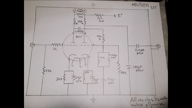
Rothwell mentioned having a go at point to point wiring in my LB thread so I reached out to him and he was incredibly gracious with his time and knowledge. He mentioned an RCA design (I think that’s what it’s called) from Valve Wizard. They used to make PCB’s but they’re no longer available and to be honest I want to have a crack at the wiring point to point instead.
I’m expecting a huge amount of learning but I’m hoping I can make something reasonable and quiet, especially with some help from the experts here.
I’ve been doing a tonne of reading, checking the schematic and parts list and I think I’m mostly comfortable with it, at least enough to think about how I’d start the process.
I’ll also build a cabinet from scratch too as I’ve done with my friends chassis as I want that level of satisfaction too. 3mm Alu and hardwood ends (the plastic still has to be pulled off the Alu):

If I can get it quiet enough with some general tubes, I’m toying with the idea of buying some really nice Telefunkens")
I’ll build the amp with 12AX7’s and an AU7 for the cathode, also based on Rothwells recommendation.
The only part that confuses me is the power supplies. I’m pretty much ok with the HT supply and I’ll hunt down a good quality 300v transformer that I will try and shield with a metal divider in the chassis.
The one that really has me stumped is the heater supply. I’m pretty sure I want to go down the rectified DC path for the heaters to eliminate any potential hum but I’m not clear on the parts required for the DC rectifier and also what sort of transformer is required to properly supply the rectifier, 2x AX7’s and an AU7.
My Little Bear looks beautiful and I’ve had such fun making it, but I long for something quieter and I want the satisfaction of knowing I built it myself. I put a lot of time in to my preamp and even relocated the transformer into a separate chassis but I’m still cursed with hum at a level that’s simply not enough for the resolution of my system, especially with a HOMC and some quieter records where I want to crank the volume a bit. Generally it’s fine, but my system is working so well and sounds so good that “fine” is not good enough anymore.
Rothwell mentioned having a go at point to point wiring in my LB thread so I reached out to him and he was incredibly gracious with his time and knowledge. He mentioned an RCA design (I think that’s what it’s called) from Valve Wizard. They used to make PCB’s but they’re no longer available and to be honest I want to have a crack at the wiring point to point instead.
I’m expecting a huge amount of learning but I’m hoping I can make something reasonable and quiet, especially with some help from the experts here.
I’ve been doing a tonne of reading, checking the schematic and parts list and I think I’m mostly comfortable with it, at least enough to think about how I’d start the process.
I’ll also build a cabinet from scratch too as I’ve done with my friends chassis as I want that level of satisfaction too. 3mm Alu and hardwood ends (the plastic still has to be pulled off the Alu):
If I can get it quiet enough with some general tubes, I’m toying with the idea of buying some really nice Telefunkens
I’ll build the amp with 12AX7’s and an AU7 for the cathode, also based on Rothwells recommendation.
The only part that confuses me is the power supplies. I’m pretty much ok with the HT supply and I’ll hunt down a good quality 300v transformer that I will try and shield with a metal divider in the chassis.
The one that really has me stumped is the heater supply. I’m pretty sure I want to go down the rectified DC path for the heaters to eliminate any potential hum but I’m not clear on the parts required for the DC rectifier and also what sort of transformer is required to properly supply the rectifier, 2x AX7’s and an AU7.

 Untitled
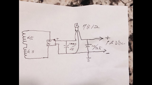 Untitled

