Is your unobtainium power switch worth $5 and an hour or so of your time?

A little better schematic, with a couple of part numbers that I've sourced, even though the only part I've used so far is the smaller TO-220 part. Still, I had a Kenwood KA-8100 here with a fried power switch and after managing to get the switch working well enough to trigger the triac, installed the device as shown in the attached schematic and it works like a champ.

I'm working on a couple of Yamaha B-2's next, and plan on adding this mod in a similar fashion.

Edit: The server is barfing pine needles at the moment, so I can't get the schematic uploaded. I'll edit this post with the scat as soon as the server is officially 'out of the woods'.

Edit 2: Got it...I think...

Edit 3: Got a few Q's on this, so I'll mention this here...the location of the load (at MT1 or MT2) is not important...Littelfuse makes that clear in their application notes. But, triggering should always take place between the gate and MT2 (and even this may not be critical, but I prefer to follow at least one standard).

I am handy and brave with a solder iron, but am technically illiterate in reading electronic schematics (even as simple as this one from EchoWars), can someone fill in the blanks for me as to where the resistor goes, also looks like there is a cap in the mix. Size rating would also be nice...thanks.

I've got a 70's Akai receiver with an arcing power switch that I want to try this on. Awesome remedy!

Sorry, the original schematic is on page 3 of this thread.
 
Last edited:
The R/C (right side of schematic from MT1 to MT2) on that schematic is not needed or desired with the Alternistor.

The 100 Ohm is in series with the gate and goes to one side of the power switch. If the original switch has the customary filter - maybe just a cap - remove it. 1/2W is fine for the resistor.

The 218X configuration has loops in the ends of the leads that you might like.

Don't get carried away with too high a current Alternistor unless you need it. Bigger units take more gate current and if you have a really damaged switch you just patched together that's one of the trade offs.

RL load is the power transformer.
 
Turnitup there are very nice pics from k7sparky detailing the triac install. Shows the wiring very clear from all points. I was able to do this mod to my Lafayette thanks to his dumbing it down for me. Saved me a lot of money not having to ship it off.
 
Thought I'd give this thread a well deserved pop and report on my uses of this mod. In my Marantz 3250 I've used this for almost 2 years and it has worked flawlessly. I've got 3 of the triacs in it as I modified the speaker switches to become outlet switches. I just put a triac in my newly acquired Sherwood S-7200. These are on the power switch killer list as well. If your on the fence I'd strongly recommend jumping in, this is definitely worth doing.
 
Yup k7 sparky is the man and this mod is great. My Lafayette lr-9090 is very happy with this mod, very helpful person and always responds to pm even if its a no brainer to him he would take the time to help me out and I cant thank him enough for that. Come to think of it all you guys here are pretty cool. Bob.
 
I'm going to do this on a Sherwood S-7200. What is the best triac to use?
Q6030LH6?
Q6040J7TP?
Q4040K7TP?

Now to see if I can salvage my switch.
 
What is the NP AC power required rating on your Sherwood and do you plan on leaving or adding switched 120 VAC outlets?
With the TRIAC all that is at stake is a few $ part in case of failure. All your power switch is looking is a few ma. Worst case is you Nuk the TRIAC back to beach sand.
Take time and patience with the power SW repair. Do NOT file switch contacts - ugly is good. The arc pin points are what make the initial contact. Scrubbing bubbles will clean off all the carbon, just let it dry a long time.
 
Thanks for the reply.
I believe the receiver is only rated for 36 watts output. The main power is fused at 3 amps. I don't exactly know the peak current at turn-on if the caps are fully discharged.
I am fixing this for a friend but I will tell him NOT to use the switched outlet, or I could disconnect it too, he would be fine with that.
I will leave the contacts as they are and just clean the carbon off. Right now it is stuck at full-time On.
 
Stuck ON?? Does it otherwise work OK?

If not then first thought is the PS contacts are welded so look for what caused that. "What fails is usually not what kills" Guess (SWAG) is shorted output transistor, PS rectifier diodes, shorted filter caps. If the fuse doesn't blow now it is probably something melted like a trace to isolate the short. Multiple failures

Take your time and worry the contacts apart - watch the thin moving arms.
Take plenty of pictures so you will remember how to put it back together.

With the TRIAC there is no worry about using the switched outlets. Worst is a few $ TRIAC

The inrush for charging caps most likely will be limited by the subtransient reactance / inductance of the transformer.

A quick take on the Littlefuse manual
60 = 600V
30= 30A continuous - trip a 20A breaker fed with #10 AWG
WAY overkill and larger takes more gate current 30A looks like 50mA for a 40A 50 to 100mA.
That said, if you think the repaired switch is good for a 50 to 100 mA resistive load use any of them that make your wheels squeal.

I am not an Littlefuse AP engineer or even have any stock in Littlefuse just an ORF from control systems. large drives and dabbled in power delivery mostly 13.6 KV and under.

I like to buy a quantity so I get a better price each so tend to get more A and higher PRV than I need.

SOOOO I usually get 400V+ so I am over designed for a 220V home / my applications.

With a 3A fuse you could live with a 3A TRIAC. Personally I would 300% it. Since I keep a few on hand I would go with 20A It will trip a 14AWG circuit 15A breaker and just yawn. But then I like a 454 Casul.

Now to the leads. Sometimes I like the straight lead and sometimes the loop end leaks - depends on which side of the bed I wake up on.. I sleeve all leads with heat shrink or fiber glass. Been burned by my fat fingers toooo many times.

That is probably TMI :blah:

I use Q4025L6 for almost anything. 400PRV 25A continuous. Darn hard to believe the specs when you look at the itty bitty things. Other knowledgeable members use higher rated ones. No one correct answer - if it fits it ships :D

If you favor leads with loop ends pay the extra for the J6 package.

Depending on your favorite supplier, is higher voltage or current is cheaper? go for it!:bigok:

Hope that helps a bit:)
 
Last edited:
Thank you very much. That gives me everything I need to pick a triac for this one any some others I have in mind too.
The switch contacts were just stuck together pretty lightly, not really welded I don't think. There wasn't much spring at all to pull them apart. Maybe I'll bend the arms very carefully to give it a little more spring. He has been using it by plugging and unplugging and it has been working fine for him. It was just stuck on all the time, a few bulbs burned out and the pots were all scratchy from sitting a lot. So far that is all it needs - (cross fingers).
 
I have a Hafler DH-220 amp (115wpc) with a burnt power switch. That's a very common problem with this amp so this mod seems like the trick. The original amp switch is a lighted toggle and I'd like to keep that feature if possible. Question of the day - can I do this mod and keep a functional light in the toggle switch?
 
The original amp switch is a lighted toggle and I'd like to keep that feature if possible. Question of the day - can I do this mod and keep a functional light in the toggle switch?[/QUOTE said:
I would say yes to both.
Can you repair the switch enough to carry around 100ma? If you can get it read reliably a few Ohms on your Ohm meter then it should be OK. All you are supplying is the TRIAC gate current.
The lighted requires a question. What voltage is used and does it have separate terminals for the light?
If the light is on one of the LV supplies then no mod necessary for it.
If it is line voltage I would move it to be in parallel with the transformer primary.
 
lightedswitch.jpg
The switch is toast, so I'll replace it with Mouser 629-GRL20111600. If I'm reading this right then poles 2 and 1 will switch the triac (amp), while pole 3 provides ground for the light. I guess the thing in the diagram that looks like :eek: is the light? If so, this mod will work a treat.
 
That switch will NOT make you a happy camper:thumbsdown:

The contact that switches the TRIAC gate must be isolated. The gate current spec is worst case. You Don't want any leakage to fire the TRIAC now and then or maybe a lot when you think it is off.

A quick way around that if you want to use that switch is with any small interposing relay. SPST or SPDT or whatever 120 VAC coil you have in the junk box. Use the dry contact to turn on the TRIAC.

The TRIAC turns off on a zero crossing so there is never a peak voltage from transformer inductance. If there are any snubbers toss them, this is not an option

This advise is for the Littlefuse Alternistor only as it is designed for inductive loads. And as I said at the beginning I don't even have any stock in the company.
 
My dreams are temporarily crushed, but we might be OK. This lighted switch has a neon bulb. If it were incandescent then there would be an electrical path to the gate and problems would ensue. But a neon bulb is an open circuit until it lights up and starts conducting, so that should isolate the gate, yes/no?

If the neon light doesn't save the day, I could try to hack the switch and wire the lamp in a way that isolates the triac. I'd expect that effort to result in nothing more than a busted switch, so my backup would be to get a non-lighted switch and just drill the face for a separate power-on LED.
 
Last edited:
I grabbed a SWANN series 44 orange lens one out of my junk box and popped the rocker out. One of the neon is tied to the plunger that operated the toggle in the bottom terminal 2 on your drawing. The other to a 47K resistor that is bend around and contacts the light terminal 3 on your drawing. The bulb is in the center of this switch so no clean way to fish it out and the lead would break from flexing. With this switch Terminals 1 & 3 are N/C in off position. 47K is what I remembered as a normal neon series resistor for 120VAC applications.

I have no idea what hooking 47K from the gate to AC common would do nor would I like to find out.

I see non lighted ones a line down at about half the price.

Also at the bottom of the page there are "Indicon" that have color plastic showing when ON. 629-AA111B11 that is the same hole size
 
Non-lighted switch it is! Thanks for the P/N - that one looks good. If I ever feel the need I'll just pop in a pilot light that isn't wired to the triac. Thanks for this thread by the way - universally applicable to all makes/models. Its up there with the most useful on the entire site.
 
I know the horse is already dead, but I can't resist flogging it a little bit more. As I've stated several times before in several threads, triacs in transformer primaries are not completely without risk. I have empircal and anecdotal (and expensive) evidence dating from the early 1980s regarding this, but that part of the horse has nothing left to wail upon. What we in the rest of the world have done is to limit inrush by other methods. Pioneer was on to this several decades ago with their larger units, using a ballast resistor and relay. It was a good effort, but somewhat cumbersome. Still, it was effective and good enough to be copied by several other makers. They evidently "borrowed" the idea from Ingersoll and Cincinnatti Milacron from a 1960s design in EDM power supplies, and possibly from something even before that, albeit on a smaller scale. Transformers have since become "more efficient" (read "cheaper") by using less iron and less copper. As a result they now have so little CEMF on initial energization that even a Form Factor D circuit breaker can occasionally trip. It's become so bad that even NFPA altered their protection ratings for these small transformer primaries in the 2008 re-write. That makes them much like the even smaller transformers we see in vintage audio linear supplies.

Fast forward to today (or about five years ago) and a more simplified solution became common in controls. NTC thermisters are available in very large energy and current capacities. Since I had several panels in my shop last week I thought I'd gather some data once again. I tried three ratings of thermistors in primary feeds. One was right at the minimum dissipation for the calculated inrush, one was well within a comfort zone, and one was complete overkill but had insufficient resistance to limit inrush as well as we would like. The one which was light eventually split from excessive heat. The one which was best suited was analyzed in more detail.

The result was that after numerous energization cycles on intentional overvoltage it still limited current effectively and easily passed the FLA rating without heating or excessive voltage drop. Energizing a 460V 1.5kVA transformer primary with the supply test panel feeder taps set at 505V (10% overvoltage) the thermister still limited peak inrush to less than 7A instead of the "naked" system inrush of over 55A.

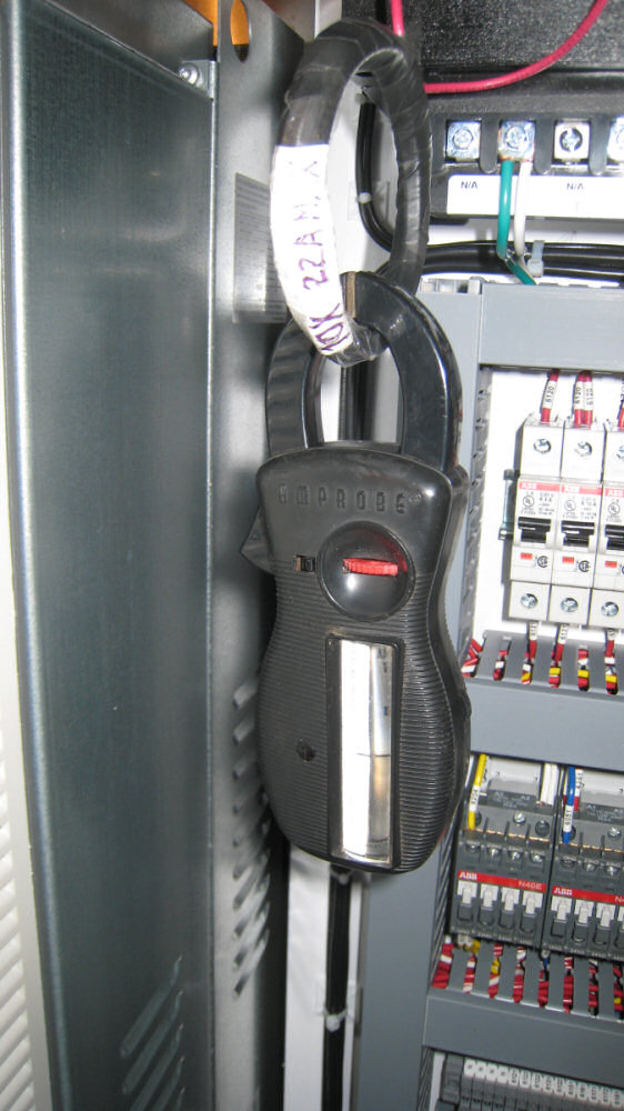
ThermisterCurrentPeak.jpg


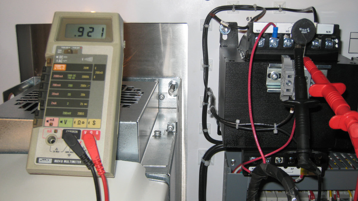
At nearly full secondary load (12A from a 2,000 BTU panel air conditioner) the voltage drop through the thermister was less than one volt (0.2%) and it showed no heating.

ThermisterVoltageDrop.jpg


Translate this to the primary of your 1kVA transformer in a 300WPC amp and maybe some will grasp what I've been suggesting.
 
where is that transformer anyway ????
 

Attachments

  • 00-girl-up-pylon.jpg
    00-girl-up-pylon.jpg
    39.4 KB · Views: 103
Back
Top Bottom