Is your unobtainium power switch worth $5 and an hour or so of your time?

Using a NTC thermisters on a patched together original switch will still blow the @@##$ out of it.

If a final transistor, filter cap, diode, etc goes or if your xx plugs the toaster into a switched outlet your power switch is still likely toasted.

I'll stay with a cheap replaceable TRIAC using around 100 ma gate current.and save my switch to play another day.

It appears you are using a clamp on with a needle block. The needle block was developed long ago to get an average long term inrush. Analog meter movements take a long time to get the needle moving and then wildly over shoot caused by the mass of the movement. The needle block was developed to hold the needle at the high average sensed by the movement.

In use, we jacked up the block to get the needle to just wiggle off the stop on a start. Motor or transformer.

If you are using the needle block and measuring transformer in rush, my guess would be about 10X for actual value of the first 3 or so cycles depending on where on the sin wave the contacts make and what the contact bounce / burn time is. The NTC may limit it, don't know never studied the data sheets. Just a guess as never instrumented a little transformer. I think the smallest I ever instrumented was around 500KVA with a Dranetz disturbance analyzer in the 70s.
 
Specifically, the NTC thermistor limits peak inrush to less than 7A on a loaded 1.5 kVA control transformer fed by overvoltage (505VAC on a 460V system). It presents negligible resistance to the supply circuit at nearly full load, creates NO switching noise and does not distort the AC wave at or near the zero level even in the least since it is a resistance, not a pair of semiconductors turning on and off. The result is that there is no appreciable arcing at the switch contacts on make or break, and that's what erodes contact surfaces.

I know it's not less than 30 words, but I'm a heavy tipper.
 
where is that transformer anyway ????

That transformer is in an ultra-low harmonic drive panel, powering the electronics and magnetics for the drive control and interface, as well as powering the panel air conditioner since the enclosures will be mounted outdoors in the east Texas heat and sunlight. In short, it MUST operate under all conditions of weather and power. It's one of many to be installed to replace the noisy, triac type VFDs which are raising Unholy Hell with their power systems (did I mention i HATE switching power supplies?) within their facility. Since they chose badly once before, I get to profit. As my father used to remark, "The only thing worse than spending too much is spending too little."
 
I'm just busting them on ya .. I thought I'd throw a stupid question in ...
 
Been using the two thyristors as mentioned in Post #34 now for nearly three years on big amps where there's no mechanism for inrush limiting and have experienced zero issues. On the last 4 or 5 units, I've omitted the snubber between MT1 and MT2. Flawless operation.
 
That's a good situation. That demonstrates that there is more than one way to skin a cat, or overcome this switch failure concern. The relay is another. For a switch that is already toast and is limping the thermistor may not be the best solution since the switch will ultimately carry all the load. For a healthy switch subjected to heavy inrush, it can prevent damage. In place of a factory soft start circuit, it works well.
 
Nearly all the units I've done employ a toggle-type switch for power. If I am to retrofit them with a thyristor, I'll generally disassemble the switch to make sure the contact surfaces are clean and carbon-free.

Just got done with a Kenny KR-9600. The power switch was working, but on disassembly it was evident that the contacts were not in very good shape. But...after some wire brushing and some sandpaper, they're plenty good enough to carry a few hundred milliamps to power the thyristor.

Just mentioning this because you cannot assume that your 40 year-old power switch is 'fine' just because it works without this mod. Really cruddy contact surfaces can starve the thyristor, causing it to trigger off and on at high currents. I'd not think this a good idea.
 
Hello. I've tried the Triac simplest circuit without any by-pass, at a tube amplifier to avoid the power off "thump". It works OK, silent power off, but I get a switching noise at the speakers, barely audible, but present. It's not there whithout the triac.

I'm using a BT136-600 triac, at 220V AC mains.

Tried a 10mH inductor in series with the load, no change. Tried a capacitor as shown here at C50,
TRIAC_POWER_ON.jpg

with a 0.47uF and a 220ohm resistor the noise is reduced, almost gone, but still there...

Is the BT136 Triac not suitable for this audio application, or should I try another kind of filtering?
 
Thank you for sharing your mod and experience.

I just became proud owner of a Criterion Mark VII, which was the last of the Lafyaette's TOTL receivers, before closing shop and after playing with it for a week or so, it too started to develop the annoying switch arcing problem. Your work saved me a lot of time as I was going the relay route first.

You also mentioned "Scrubbing Bubbles" in your posts as a substance good enough to clean all things electronics and just wanted to confirm that its the toilet bowl cleaner. If so, doesn't it leave a film of some sort?

Thanks in advance,

Best

Soundork
 
Turnitup there are very nice pics from k7sparky detailing the triac install. Shows the wiring very clear from all points. I was able to do this mod to my Lafayette thanks to his dumbing it down for me. Saved me a lot of money not having to ship it off.

Looking for these pics. Don't see them in the thread. Can you shoot me in the right direction?
 
These things are NTC thermistors...resistance goes down as temp goes up. And the temp is a direct function of the current. On solid-state gear, 99% of which is Class aB, there's a huge difference between idle current and the current at full power, therefore a huge difference in the resistance of the device between idle and full power. All this trouble we as technicians and engineers go to in order to design big, bad power supplies is thrown out the door by introducing a non-linear component into the primary of the transformer. There are better solutions that don't involve crippling the power supply. You may also consider that not one manufacturer of high-powered Class aB solid-state amplifiers has ever used an NTC thermistor as a stand-alone current limiting device (there are designs where the NTC thermistor is bypassed by a relay after power up, which is a totally legitimate use for such devices).

Tube amps and true Class A solid-state power amps are different, in that the current drawn from the wall does not change nearly as much, and here the NTC power thermistor has a real use. But wherever they are used, mounting must be carefully considered, as these devices can get quite hot.
Thank you for that, very much and sincerely
I have long labored under the impression that once these devices, NTC thermistors designed specifically for inrush protection, had "opened"* for lack of a better term, that that was that, it's presence then only represented a small resistance value of about 14 ohms or less, depending on model
The spec sheets claim they are self-heating and once inrush current has settled, normal current is just that, normal and unimpeded by the device with a fairly substantial recovery time depending on model selected.
I have only used them with tube amps but have considered them for applications such as the one up for discussion
The cooling and subsequent resistance will fluctuate/go up that rapidly on a SS amp at idle?
What are these folks using them on here? Computer power supplies? Kind of amateurish video, but they are clearly embedding these in Solid State and some sort of switching supply?:
Just no good?
They do make a big distinction between these types and those used to monitor and control temperature on the various websites (manufacturers')
Thank you for the nice post
Joe

*as in open the door and let 'em in
 
Last edited:
Simple AC Power Switch Using a Thyristor
...

I'm working on a couple of Yamaha B-2's next, and plan on adding this mod in a similar fashion.

....

Glenn, could you elaborate a bit on what you did for the B2 implementations for this? With the B2 switch that has two wires on the switched side to the load, do you simply connect both these to the MT1 on a single TO-220 and just wire MT2 and Gate as in your diagram?
 
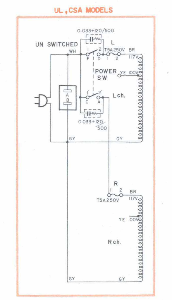
Here's the schematic of the primary:

AC_Primary_B-2_zpsywcst2mr.png~original


Note that the 'F' and 'C' side of the switch are electrically equal. Once the switch is closed, so are 'D' and 'A'.

On the B-2 I worked on, I believe I tied the wires together on one side of the switch and ran 'em to the MT2 terminal and did the same with the other side of the switch running 'em to the MT1 terminal (using some short lengths of 18ga wire, soldered and shrinkwrapped).

Shoulda took a pic, but still, this is pretty straightforward.
 
There are two points/questions I would like confirmed regarding installation of the thyristor.
1. If the original switch has the customary filter (or filters) - maybe just a ceramic cap - should that cap be removed?
2. Does the thyristor get so hot that it must be hard mounted to a metal surface in order for it to better dissipate heat?
 
1. Yes
2. Figure 1W per amp of primary current. So yes, unless you mount the thyristor to something to act as a heat sink, it'll burn up.
 
Back
Top Bottom