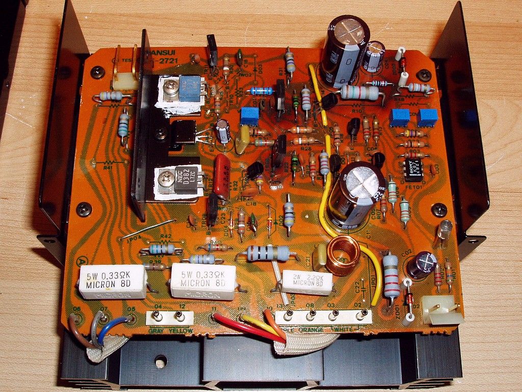
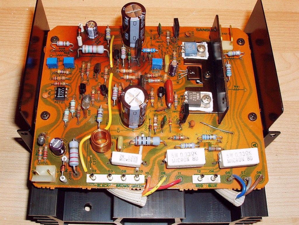
Leestereo's Restoration/Upgrade Of A Sansui AU-717

I have seen on other threads( there are many on AU-717 rebuilds) were that it was suggested that you could increase the output( WPC) by increasing the size of the 4 12000uF caps(C701-C704). I am wanting to really trick out my AU -710 . So any mod suggestion would be welcomed. I am collecting information/suggestion , ordering parts, etc. developing my battle plan before I crack the Au 710 open and start disassembling. Mark
 
C19, C20, C21 and C22, were replaced with 0.47µF stacked film types.

(C05, C06) which were 0.33µF polyester film types; these were upgraded to 0.33µF Panasonic polypropylene film types.

Similarly, C23 and C24 were ordinary ceramic capacitors at 22pF (listed as 10pF in the schematic) and these were also replaced with C0G cpacitors of the same value.

For most of the film caps and C0G caps you didn't mention voltages, since most of them are signal path are they all low voltage? ~50v?
 
For most of the film caps and C0G caps you didn't mention voltages, since most of them are signal path are they all low voltage? ~50v?
As a general rule, the signal path capacitors will be subjected to lower voltages than the power supply capacitors. The polyester stacked film capacitors are typically available rated at 50V or 63V. For the polypropylene capacitors, use the smallest capacitor that will fit the available board space (which is often the lowest voltage rating). For C0G capacitors you can use 50V or 100V rated ones.
 
Very good. But how do you account (or allow) for higher uf values when the factory assigned the values that were in there? Higher voltage is one thing. But uf value is another. :lurk:
 
Would you be willing to look over my cart and see if the parts are ok or if I should go with different parts?

http://www.mouser.com/ProjectManager/ProjectDetail.aspx?AccessID=f1216221b5

Thanks
Generally, your parts order is OK. But I did notice some possible issues:
*check the quantity needed for 2 Driver Boards.
*the 0.47µF film capacitors you have in the Mouser cart are too big, use WIMA stacked film here
*some of the film capacitors the 10% type, 5% or lower is preferred
*the 27.4kohm resistor you have in the Mouser cart is back ordered
*the 150ohm resistors should be metal film types
*the 470µF 16V Nichicon ES may not fit on the phono board, use Nichicon VP
 
Very good. But how do you account (or allow) for higher uf values when the factory assigned the values that were in there? Higher voltage is one thing. But uf value is another. :lurk:
If I understand your question correctly, you are asking if increasing the capacitance value from the stock value is permissible. In the vast majority of the cases, there is no problem increasing the capacitance rating of the local decoupling capacitor, especially for small values less than 1000µF. IMO, a 2X-3X increase is acceptable for most small capacity capacitors whose purpose is solely DC filtering. In these cases, the extra load on the power supply transformer and diodes is minimal. However, the extra load would be a consideration when large main power supply capacitors are to be replaced; in that case, a more conservative approach is warranted, e.g., the stock main filter capacitors for the AU-717 are rated at 15,000µF and increasing them to 18,000µF (a 20% increase) would be acceptable, but beyond this value may be inviting problems.

The original capacitance rating and types (e.g., electrolytic vs. film) specified during manufacturing were often limited by capacitor technology of the day, the cost of part and the physical size (finite space available on the PCB). I am certain that the original designers would have opted to use today's better parts had they been available or had not been constrained by profit considerations. Generally, today's best capacitors are often much better than their vintage counterparts and it is by leveraging this modern capacitor technology (e.g., long life/low ESR types, stacked film types) that the sound and reliability of vintage stereo pieces is often improved to better than when they were first manufactured.
 
...and a side effect of the larger capacitance value for PCB mounted wire ended electrolytic capacitors (providing you know what you are doing), is that they more closely match the hole spacing of the originals, and thus reduce or eliminate the strain in the component leads and their seals.
 
Last edited:
Can I reuse the 2.2uF bypass caps on the main filter caps or should I order some new ones? I'm doing a full recap of my AU-717, but forgot to order the bypass capacitors.
 
Yes, you can reuse the 2.2µF polyester bypass capacitors if they are in good condition; alternately, you can leave space on the main capacitors for an upgrade to polypropylene capacitors at a later date. Also you can increase the size, e.g., 4.7µF.
 
Great thread , I am working on a AU-717now and on the tone control F2720 , C15 &C16 are not mentioned in the text (am I missing it ?) from the picture it looks like they were upgrade from 10uf @16v to 10uf @35v low ESR type.
Also I have a question, same board I don't any 10uf @35v BP/ES caps for C21,22,45,46 I have 25V &50V .They both fit but is 50v to high for the signal path ?
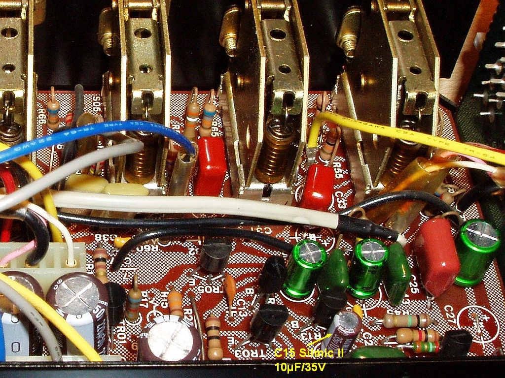
On the F-2720 board, the capacitors C15 and C16 were replaced with audio grade types (Silmic II, 10µF/35V). In a blow-up of the original picture below, you can see the capacitor C15. But it was inadvertently not mentioned in the accompanying text. Regarding C21,C22,C45 and C46, use the 10µF/25V or 10µF/50V that you have on hand.

F2720%20C15_zpsqjp6y8lk.jpg
 
moving right along here ... I couldn't without moving components on EQ board get the polypropylene caps in at C27/C29, C28/C30. So I use 2 Silmic II caps (10uf/50v) in series like the originals and I replaced the mylar bypass cap with a Wima polypropylene cap ,orignal value.
How come the capacitance was lowered on the amp/ preamp switch , from 5.0 uf to 2.2uf ?
 
Last edited:
moving right along here ... I couldn't without moving components on EQ board get the polypropylene caps in at C27/C29, C28/C30. So I use 2 Silmic II caps (10uf/50v) in series like the originals and I replaced the mylar bypass cap with a Wima polypropylene cap ,orignal value.
There isn't really enough room for large polypropylene film capacitors as replacements for C27/C29 and C28/C30 on the F-2723 board. However, 4.7µF stacked polyester film types (e.g., WIMA MKS2 or Kemet R82) will fit in the space originally occupied by the C35/C36 polyester bypass; see earlier post #20 for picture. Alternatively, a single 4.7µF Nichicon ES bi-polar electrolytic capacitor can be used to replace the original polarized capacitor pair and the by-pass kept.

How come the capacitance was lowered on the amp/ preamp switch , from 5.0 uf to 2.2uf ?
The impedance of the power amplifier is 50kohm, and with the 5.0µF electrolytic capacitors in the high pass input filter, the F3 is 0.64Hz; with the replacement 2.2µF film capacitors, the F3 increases to an inconsequential 1.45Hz.
 
Wanted to throw out a big thank you to @Leestereo for the excellent initial write up and follow on discussion. After 2 years of working on various Marantz and Pioneer units I picked up an AU-717 for my first Sansui restoration. Definitely not disappointed. :thumbsup:
 
I finished my AU-717 LeeStereo upgrade and its sounds great, thank you Lee. I went for the new filter caps , but I couldn't find all the polypropylene film caps I needed so choices had to be made . All the fuse-able resistors in my unit were open so I never heard it stock . The glue also ate the leg
off a transistor. Grab a AU-717 if you can,the upgrade is great and the unit is easy to work on .
 
Hi Lee,

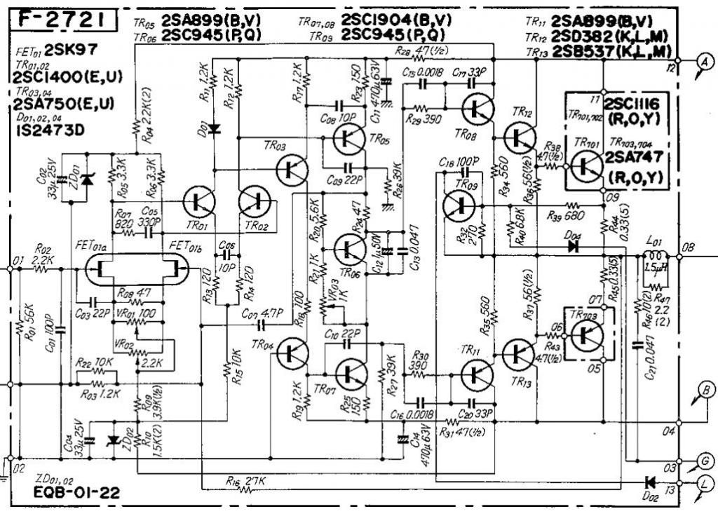
On both the restored driver assys, it appears that you installed an additional .33uF film cap in parallel with R32, a resistor that sets the bias for TR09 protection transistor.

Q1: The AU-717 schematic shows R34 is 270R whereas a 180R 1/4W is installed in several F-2721/F-2722 assys I have. Is the 180R a production change or have you seen 270R installed?

Q2: Why the addition of the .33uF film in parallel with R32?

Best,

--Bill

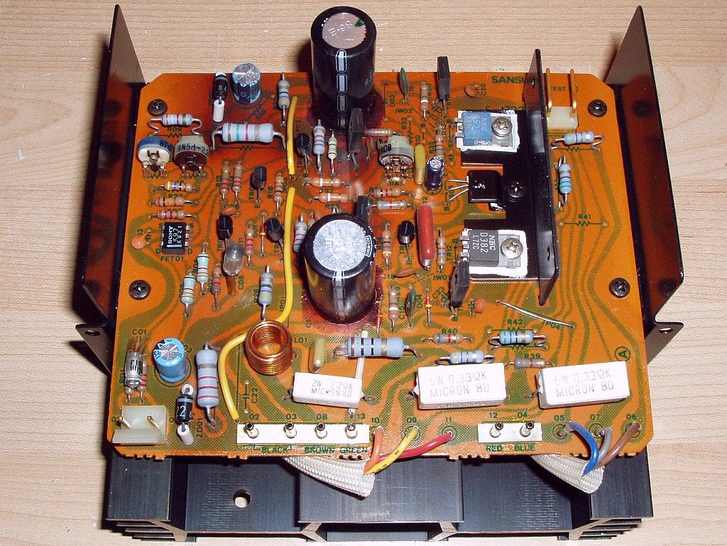
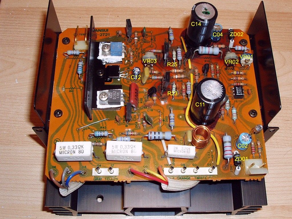
Part 3: Driver Circuit Board (F-2721 & F-2722)


The capacitors (C02, C04) which shunt the 22V zeners were originally 33µF/25V; the replacements were low ESR types rated at 100µF/35V. Also, the zeners (ZD01, ZD02) themselves were replaced with 22V/1.3W types (BZX85C22). The local decoupling capacitors C11 and C14, originally rated at 470µF/63V, were replaced with 1000µF/63V low ESR types. The C12 capacitor was 1µF/50V and was replaced with a low ESR type of the same value. The variable resistors VR1, VR2 and VR3 (100ohm, 2.2kohm and 1kohm, respectively) were replaced with Bourns single turn cermet types. The failure-prone 150ohm fusitors (R23 & R25) were replaced with 150ohm/0.25W metal film resistors. The negative feedback resistor (R16) was also replaced with a 27.4kohm/0.5W metal film resistor.

A couple of additional components were also replaced due their proximity to the C11 or C14 capacitors that were attached to the board with the corrosive glue: R15 (10kohm) was replaced with a same value 0.25W metal film resistor on F-2721 and D02 (1S2473) was replaced with a 1N4148 diode on F-2722.


Last edited:
Hi Lee,

On both the restored driver assys, it appears that you installed an additional .33uF film cap in parallel with R32, a resistor that sets the bias for TR09 protection transistor.

Q1: The AU-717 schematic shows R34 is 270R whereas a 180R 1/4W is installed in several F-2721/F-2722 assys I have. Is the 180R a production change or have you seen 270R installed?

Q2: Why the addition of the .33uF film in parallel with R32?

Best,

--Bill
Discrepancies between the Sansui schematics and the actual physical circuit are rather common. In most cases it is due to changes during the production run. I think that you are referring the R32 and not R34. The 0.33µF film capacitor across R32 is stock (I did not add this capacitor). As for R32, but I cannot confirm that it is 180ohm or 270ohm (since I don't have any pictures that show this clearly and the unit is back with its owner).
 
There appears to be a board layout difference between the driver board pictured in the SM and the pictures shown (for example) in Leestereo's restore thread.

To deltalight
Overall - don't sweat it, leave those resistors alone - it worked when it came from the factory like that.
 
Back
Top Bottom