
LEDs don't need to run on DC proper, just need a diode to block half of the AC cycle. Also, they don't need to run on 12V. Just use a resistor to limit the current.

You are using an out of date browser. It may not display this or other websites correctly.
You should upgrade or use an alternative browser.
You should upgrade or use an alternative browser.
Little Bear T10 Chassis Upgrade
- Thread starter neevo
- Start date
soundmotor
super modified
however I quickly discovered you can't solder Alu
Actually you can but it is a royal pain. One way to do it is with a big molten solder pool over the areas you want to solder. Then you scrape the areas through the solder with a stainless bristle brush. The solder protects the aluminum from re-oxidizing as you scrape away the top oxide layer with the brush. It generally works best with large areas to be soldered rather than detail work. You can also scrape and immediately flux the area to solder but you have to be lightning fast. Raw aluminum oxidizes immediately upon being exposed to air.
neevo
Super Member
LEDs don't need to run on DC proper, just need a diode to block half of the AC cycle. Also, they don't need to run on 12V. Just use a resistor to limit the current.
That's good to know. Will grab a diode and resistor today and see if I can get it done.

neevo
Super Member
So popped into Jaycar and bought a couple of 15V 1W diodes and a mix of resistors (0.5W) to test high first and see what works best.
I also bought some PCB board so I can wire it up nicely vs having loose wires and parts soldered together.
Will start with a 2K resistor, then I have 1.5K, 1k and 680 as backup options too. Resistors are cheap.
I also bought some PCB board so I can wire it up nicely vs having loose wires and parts soldered together.
Will start with a 2K resistor, then I have 1.5K, 1k and 680 as backup options too. Resistors are cheap.
neevo
Super Member
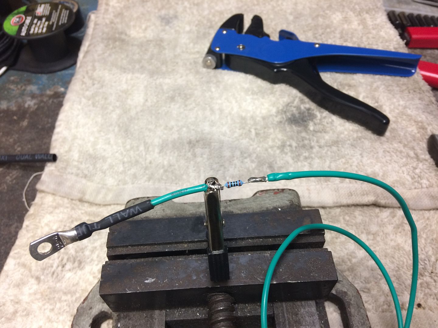
PCB cut down and have soldered in the 2K resistor to test it. If the LED isn't bright enough I will try it with the 1.5K etc:
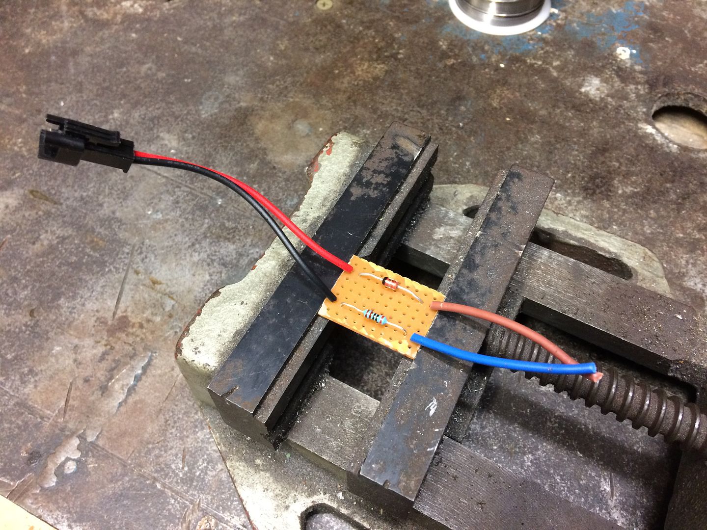
Checking out the 15V feed, I assume I wire the PCB across both of these terminals? I know from previously measuring they have 15V across them:
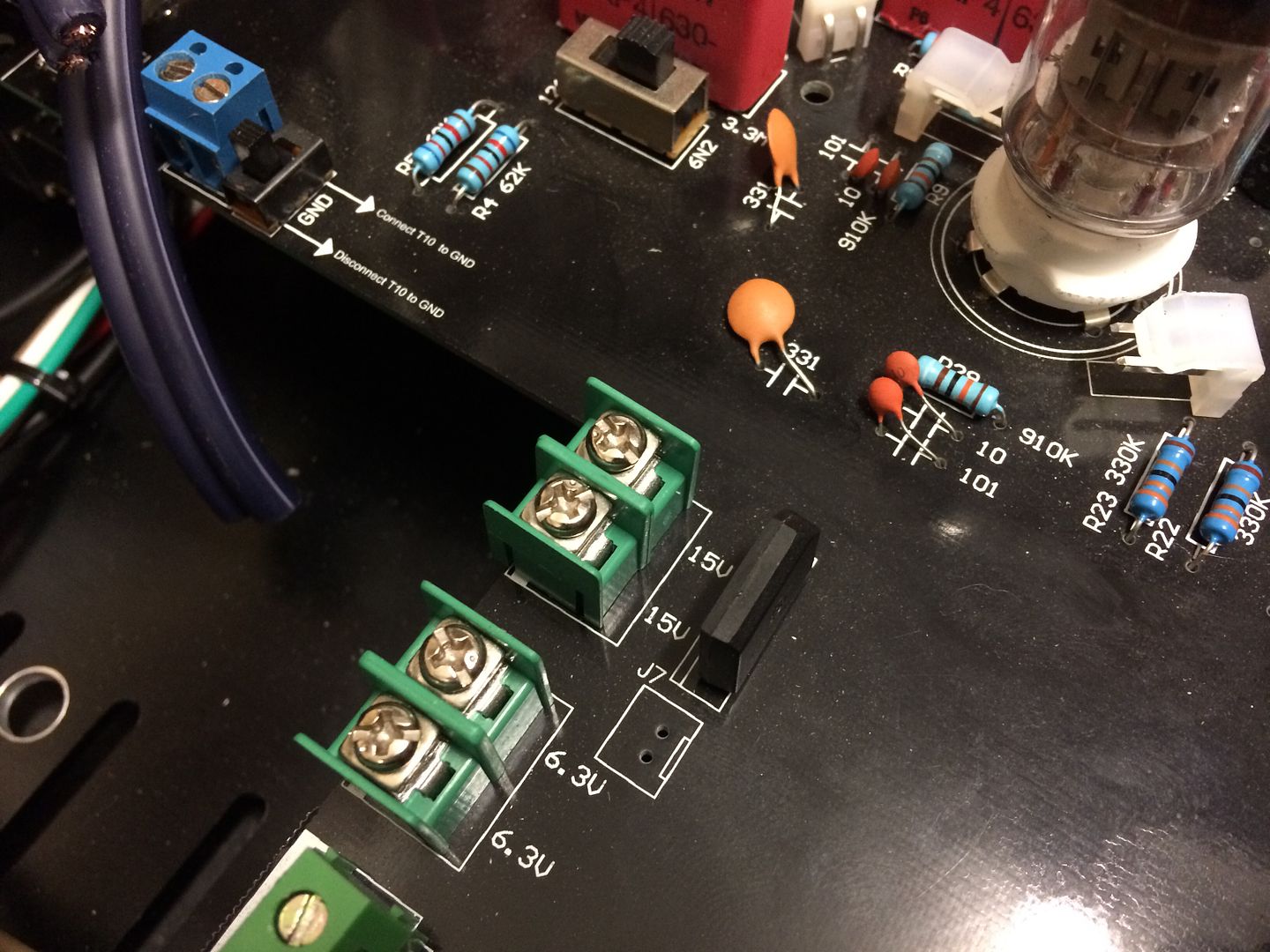

Checking out the 15V feed, I assume I wire the PCB across both of these terminals? I know from previously measuring they have 15V across them:

Last edited:
neevo
Super Member
neevo
Super Member

neevo
Super Member
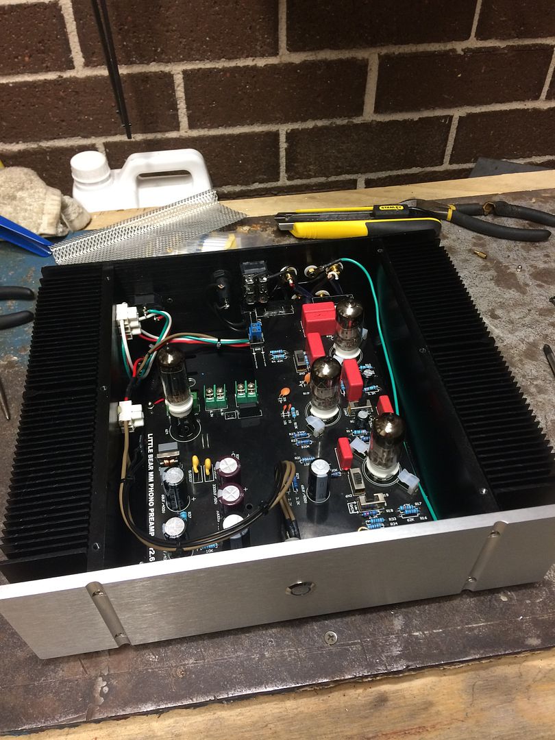
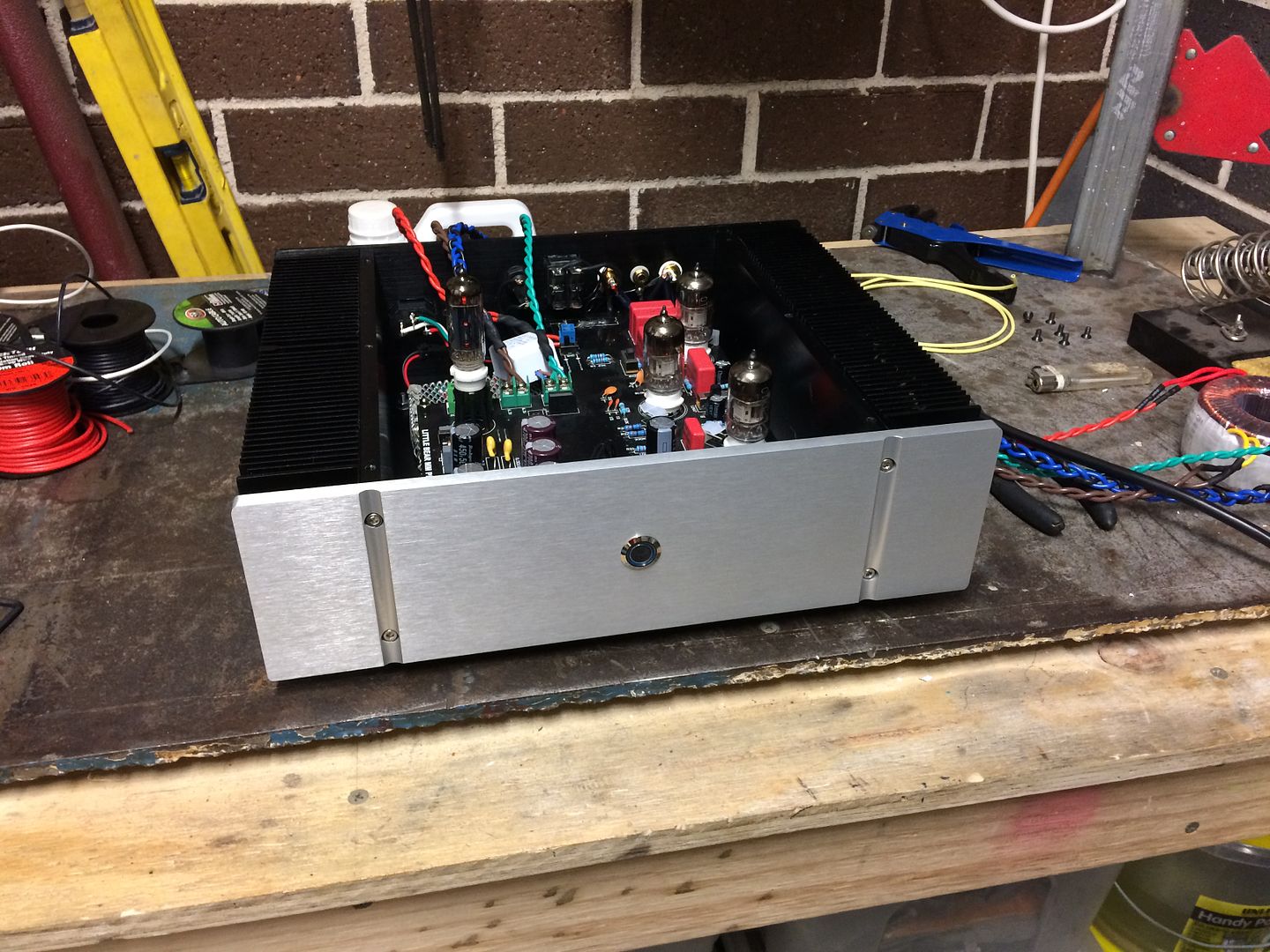
So I think I'm getting really close! Today I took the time to strip the chassis down and do some final tweaks involving twisting all power AC wires and adding in some Alu shield in a few areas. I'd like to add a bit more but need to grab some more mesh and also some wire shield at some stage.
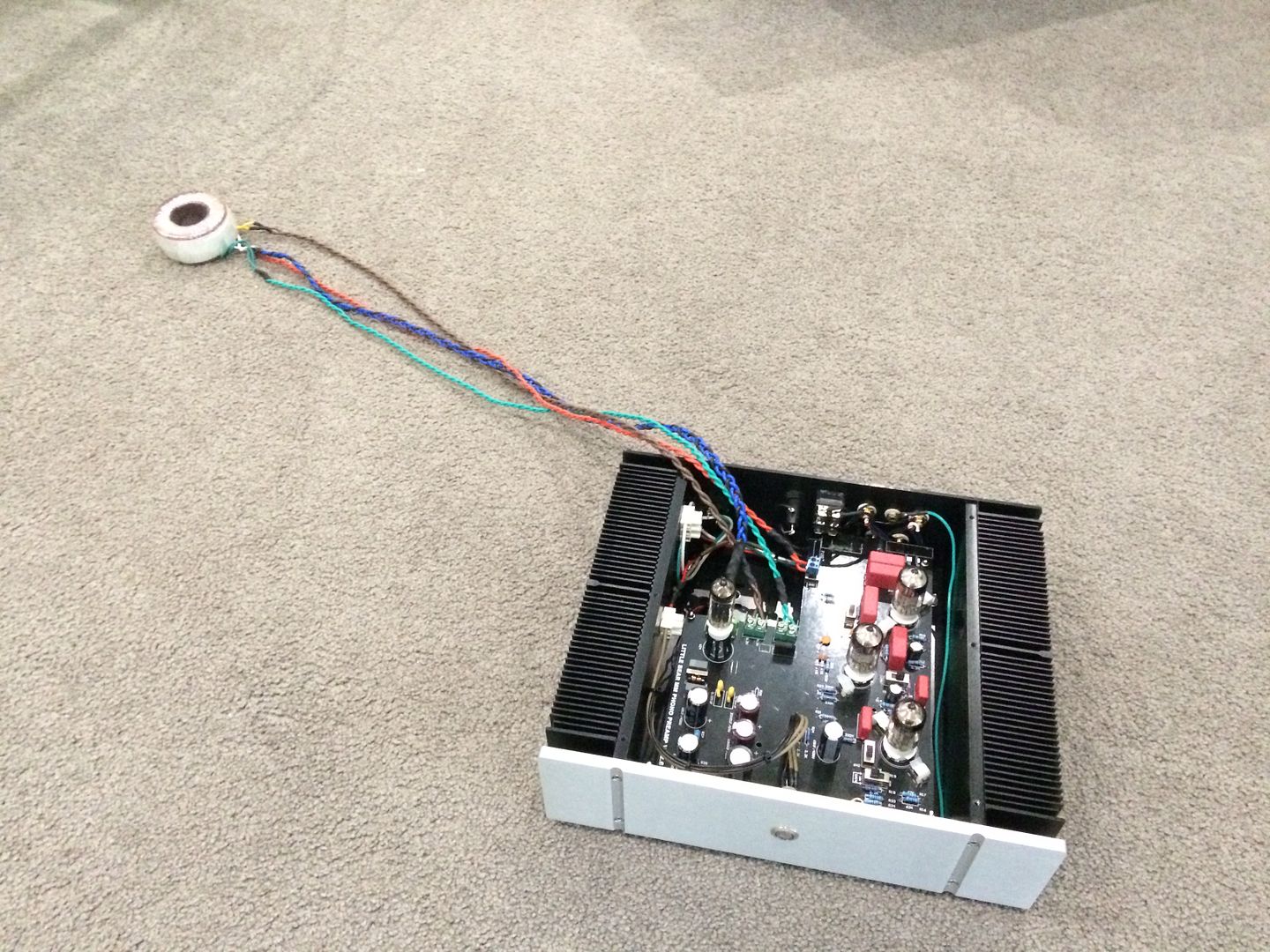
I also tested mounting the transformer remotely by extending the wires twisting each of them in matching voltages. Here it is all done:
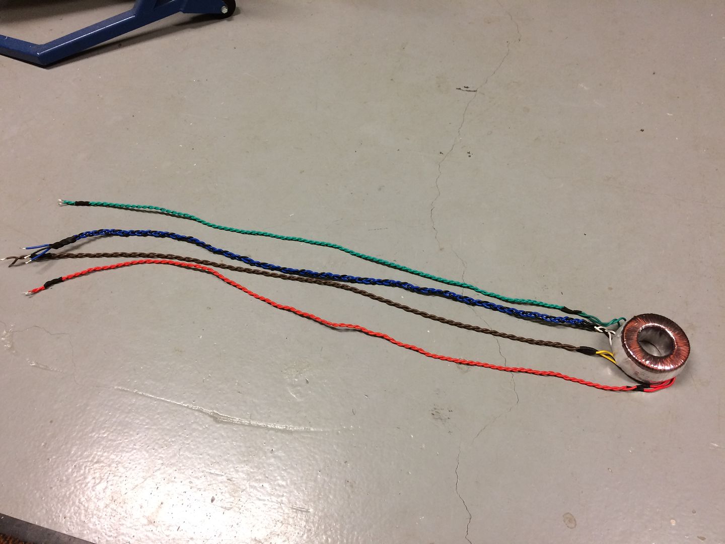
Length is perfect and should mean I can hide the transformer box just behind the unit the turntable will go on:
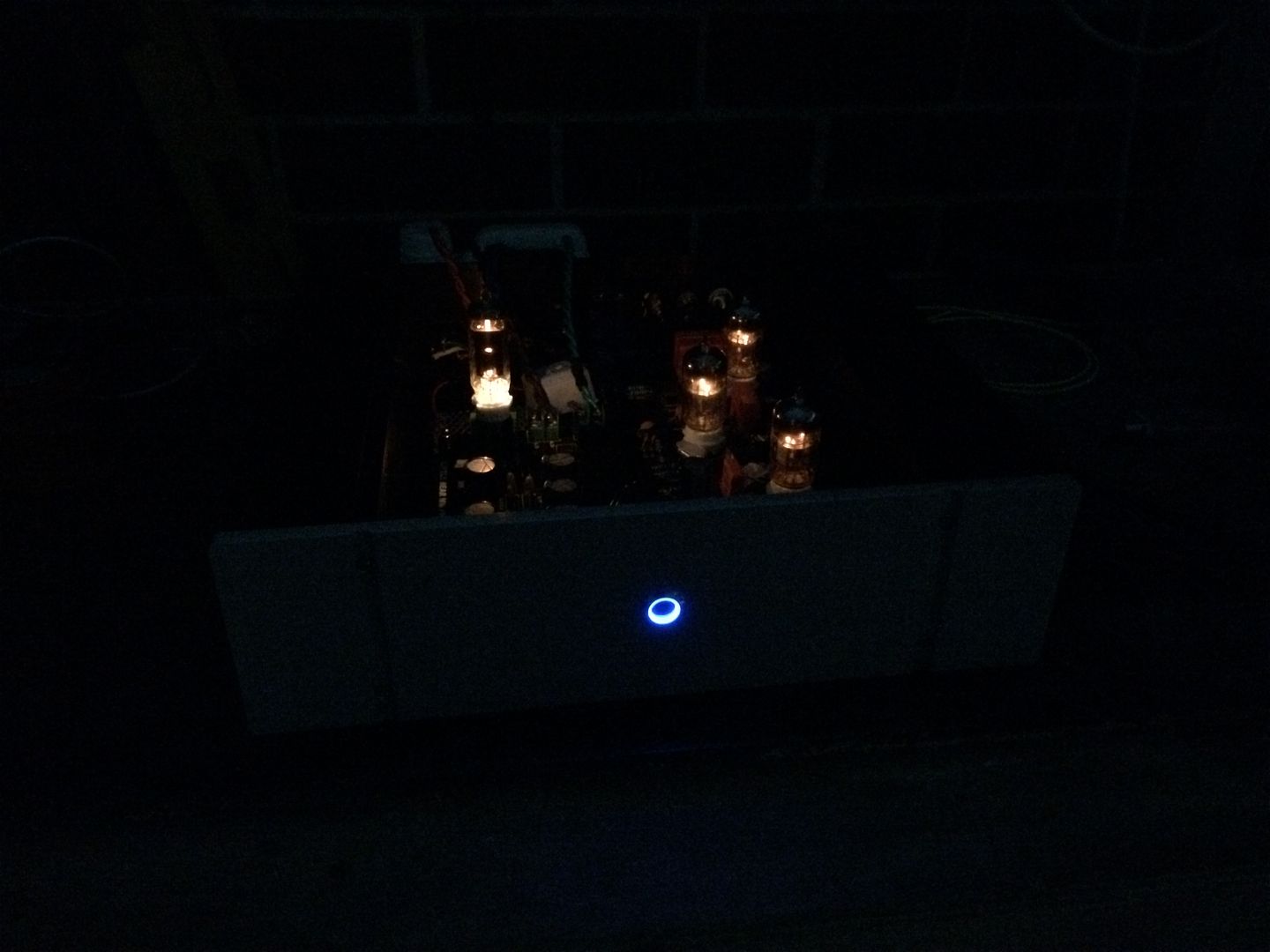
I also mounted the LED voltage reducer and rectifier I made. And I'm very excited to say it works perfectly. A warm soft blue glow that matches the chassis perfectly.
Off:
On:
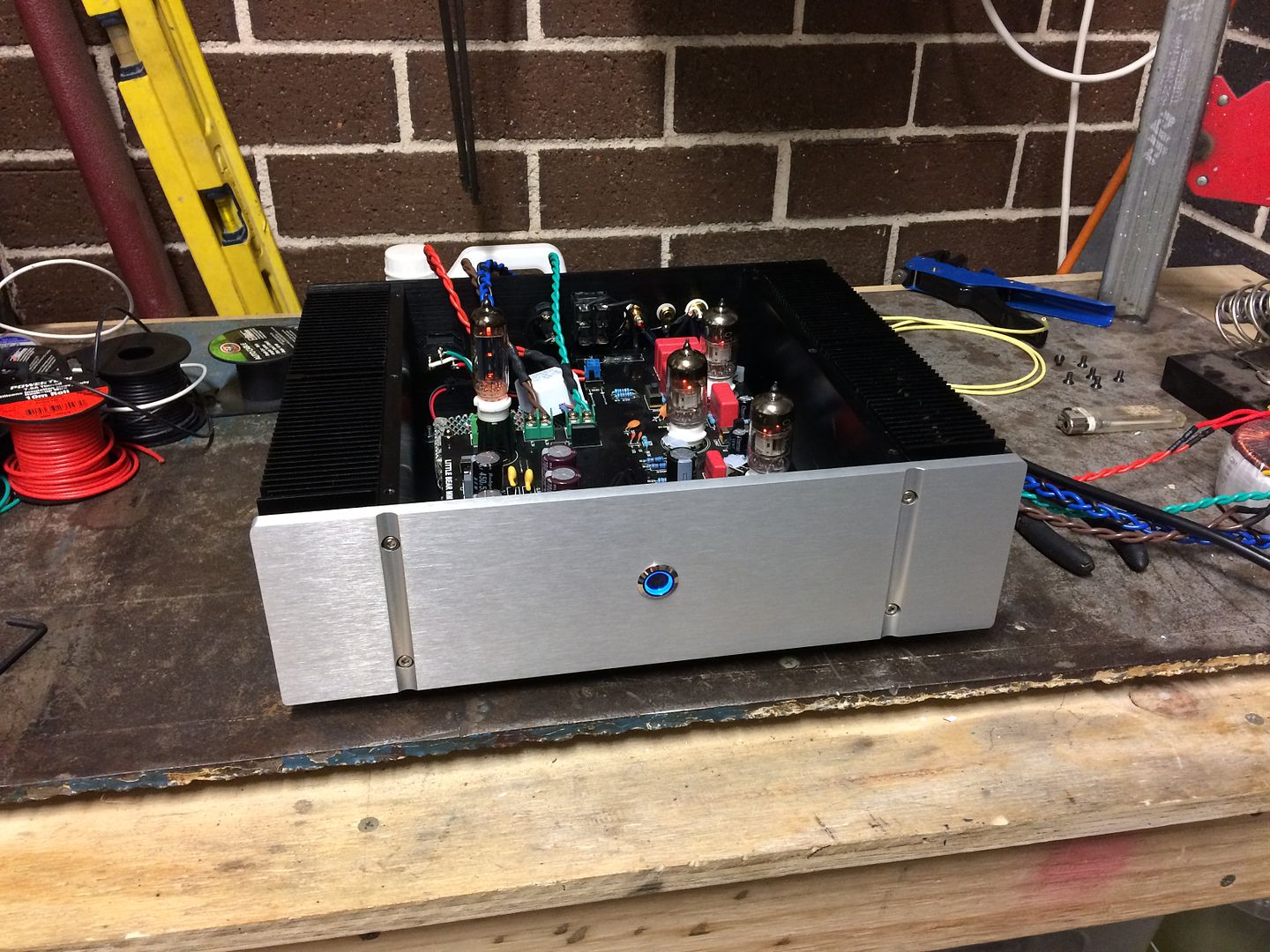
Tube and switch glow:
I also tested mounting the transformer remotely by extending the wires twisting each of them in matching voltages. Here it is all done:
Length is perfect and should mean I can hide the transformer box just behind the unit the turntable will go on:
I also mounted the LED voltage reducer and rectifier I made. And I'm very excited to say it works perfectly. A warm soft blue glow that matches the chassis perfectly.
Off:
On:
Tube and switch glow:
Last edited:
neevo
Super Member
So how does it sound?
I'm very close to having this done.The only outstanding issue is a low bass hum (sounds even worse through the sub), luckily I can completely eliminate it if I touch the chassis or put my fingers on the RCA grounds.
I assume this is a ground loop issue? Anyone help guide me on how to identify ground loop issues and potential fixes?
Reading up I see a few options:
1. Attach a heavy gauge wire between T10 and Amp between both earth connectors to try and offer a lower resistance loop for the ground loop potential diff
2. Lift a ground somewhere in a safe manner
The only outstanding issue is a low bass hum (sounds even worse through the sub), luckily I can completely eliminate it if I touch the chassis or put my fingers on the RCA grounds.
I assume this is a ground loop issue? Anyone help guide me on how to identify ground loop issues and potential fixes?
Reading up I see a few options:
1. Attach a heavy gauge wire between T10 and Amp between both earth connectors to try and offer a lower resistance loop for the ground loop potential diff
Glad this project is progressing.
No, the residual hum is not a ground loop issue. If it was a ground loop it wouldn't be cured simply by putting your finger on an RCA ground terminal. BTW, resorting to "heavy gauge wire" to cure hum problems is a sure sign of desperation. That advice should be ignored.
My guess is that the circuit is lacking a suitable faraday shield. The case metalwork should be connected to mains earth for safety. The circuit's 0V should be connected to the casework at one point only via a resistor of about 100 ohms.
neevo
Super Member
Nailed it @rothwellaudio as I was playing around with the tester to see where I had issues and found that I'd forgotten to connect the chassis to ground as it appeared the best results on the hum were when I was also touching the chassis.
Connected a single lead from the earth on the IEC in to the chassis and the hum instantly disappeared and now the amp is whisper quiet except for a slight hum that is only there at exceptionally high volume with nothing playing.
I don't have a resistor on the ground wire to the chassis, should I grab some 100 ohms or can I use a 680?
Also I can live with it but the amp when quite sometimes makes some small chirps. Any idea what they could be? Tends to be if I touch cables but then goes away.
The wire from the earth pin of the IEC socket should go directly to the chassis. The circuit's OV could be left without any connection to the chassis, but if you do decide to connect it to the chassis (for lower hum) do so via a resistor. 100 ohms is what I normally use but you could go higher. 680 ohms would be ok.I don't have a resistor on the ground wire to the chassis, should I grab some 100 ohms or can I use a 680?
A direct connection from 0V to the chassis could produce an earth loop (depending on how the rest of the system is wired).
A shared point will be fine.
neevo
Super Member
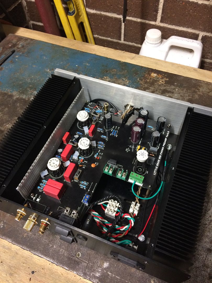
So I added the chassis mount with a 100 ohm resistor to the 0V rail of the PCB (pre heatshrink):
I also had to replace the main power connector on the PCB as the original one cracked when it tightened it up.
Am I happy? Not quite. I've got a tiny hum in the left channel that I suspect is from the routing of the RCA cables. I used thick component video cable and it's too hard to work with, so I'm going to pull it out and replace it with this:
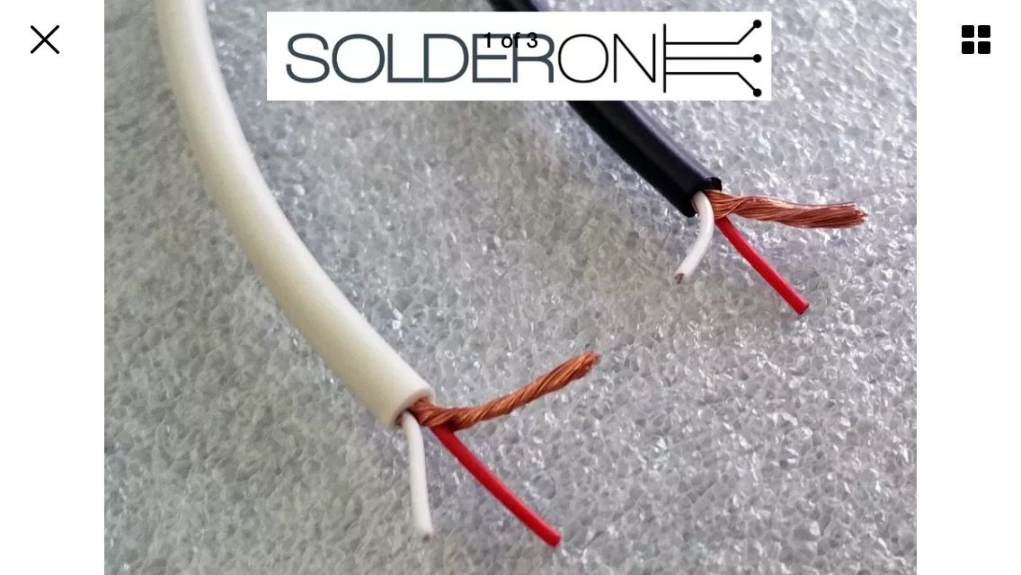
Individually shielded twin core cable. Should be more flexible and mean I can put it in a better position in the chassis.
Hopefully that fixes the tiny L channel hum. Either way the amp is sounding very quiet and if I use the high gain option then the hum is not even noticeable at normal listening levels with nothing playing on the TT (arm up but platter spinning).
I also had to replace the main power connector on the PCB as the original one cracked when it tightened it up.
Am I happy? Not quite. I've got a tiny hum in the left channel that I suspect is from the routing of the RCA cables. I used thick component video cable and it's too hard to work with, so I'm going to pull it out and replace it with this:
Individually shielded twin core cable. Should be more flexible and mean I can put it in a better position in the chassis.
Hopefully that fixes the tiny L channel hum. Either way the amp is sounding very quiet and if I use the high gain option then the hum is not even noticeable at normal listening levels with nothing playing on the TT (arm up but platter spinning).
neevo
Super Member
I think I'm done with the mods to the board. I've replaced the RCA cable and it's much thinner and easier to route in the amp. Hopefully the wire is ok for signal as its thin, but it's supposed to be good for 30V so I hope it's all ok.
Here she is in all her glory:
I've also extended the tube sockets so I can get them flush with the lid of the chassis:
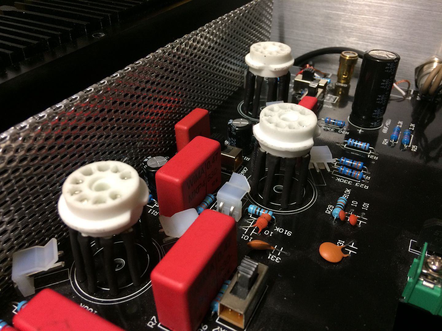
These ones will still have extra tube sockets too however as I couldn't find a tube socket for the 7 pin rectifier tube, I used 1.6mm TIG welding rod which is super sturdy. I'm also playing with the idea of using the old Alu tube covers for covering the sockets and the extensions to reduce the risk of noise.
I also redid the Alu sheild as I wanted it tidier and also the new RCA cable meant I could route it much easier:
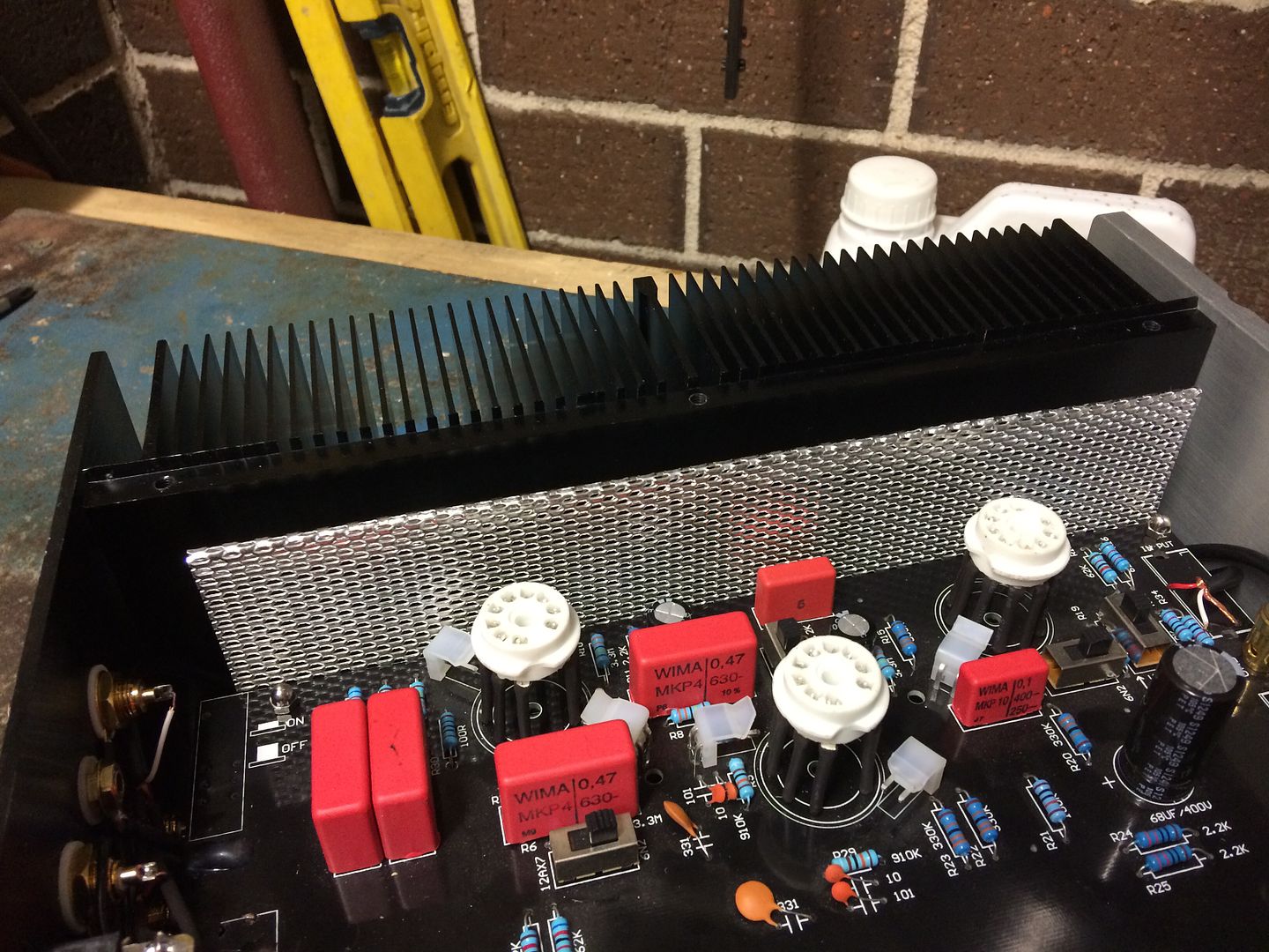
The other thing I had been toying with was making some tube guards. Now the tubes will extend out the top of the chassis they are very vulnerable and guards would protect them, plus I was hoping they would help with the look on top as it was looking a little sparse even when the tubes were in.
The auction site had some nice ones but for all 4 it would run me approx $50, so I bought some Alu stock instead and set about making my own. This way I could make them exactly the right size and I could make them thicker too as I prefer the look.
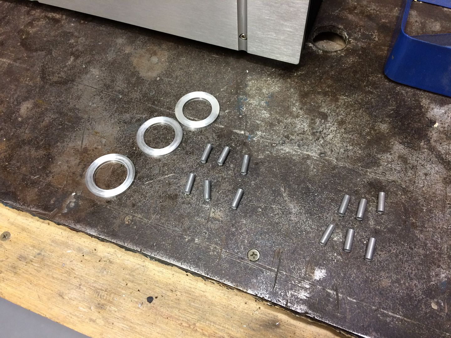
First up with making the rings:
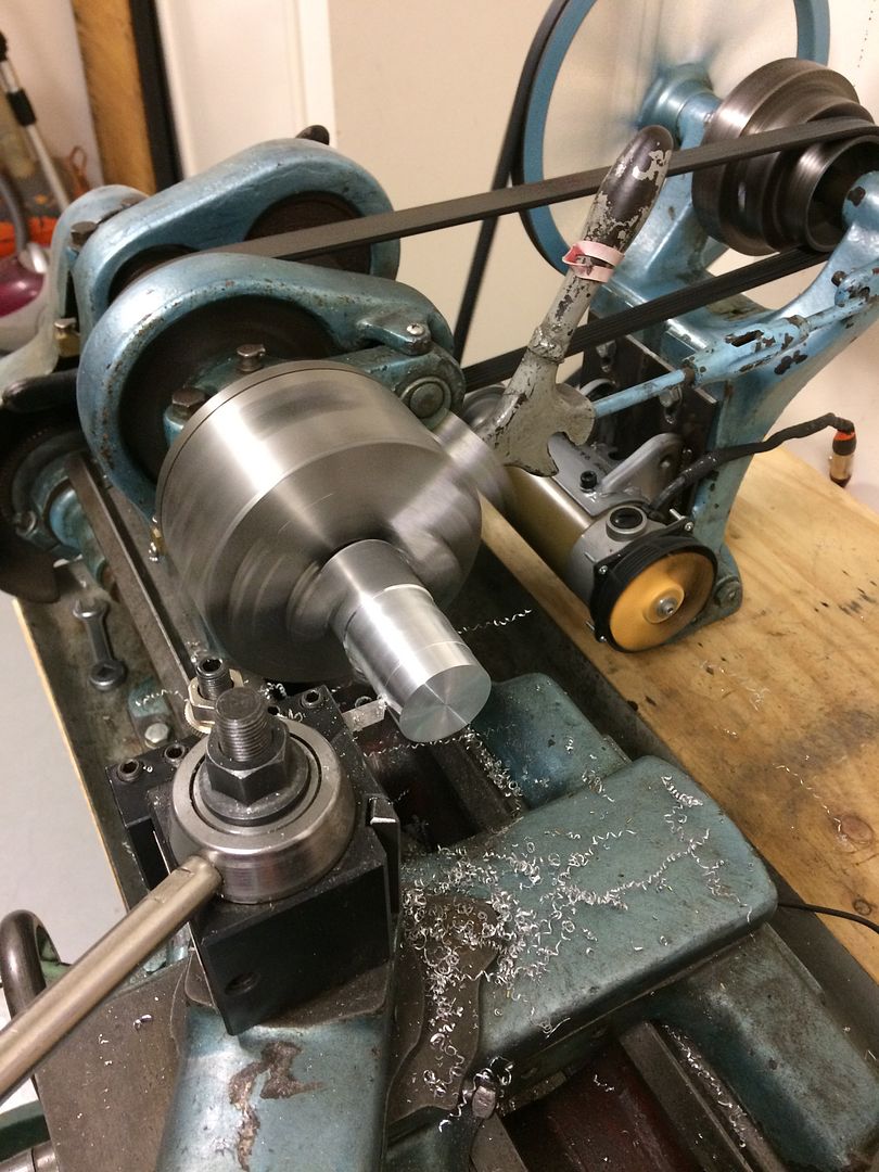
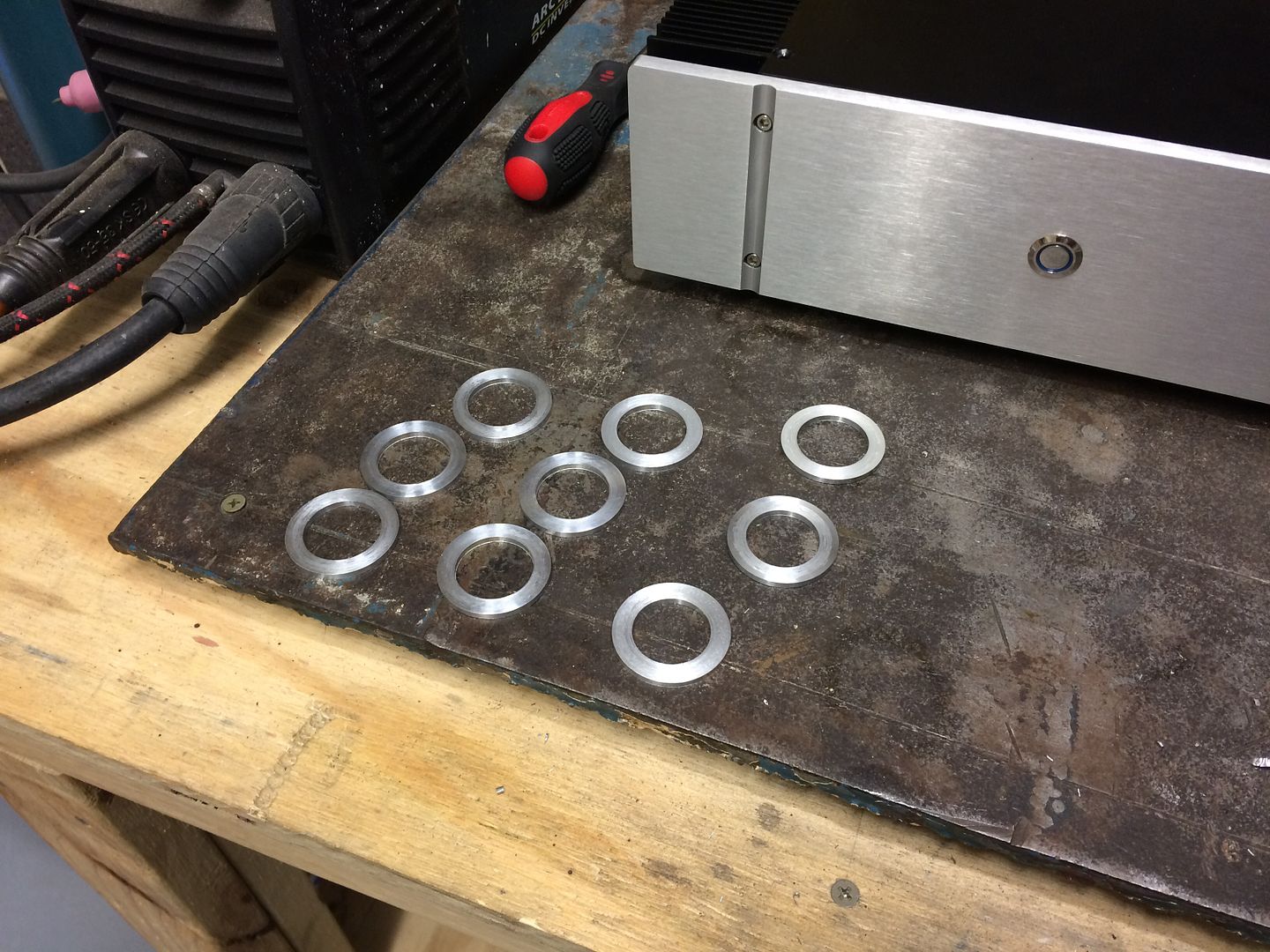
All done (only 3 sets so far as I'm going to make the rectifier the correct dimension too vs using 4 of the same):
Next up I used the lathe to trim the tube down to 15mm which had the rings in the right spot to cover the bottom/top of the tube, plus not cover the heater so I still get the glow. Rings and tube:
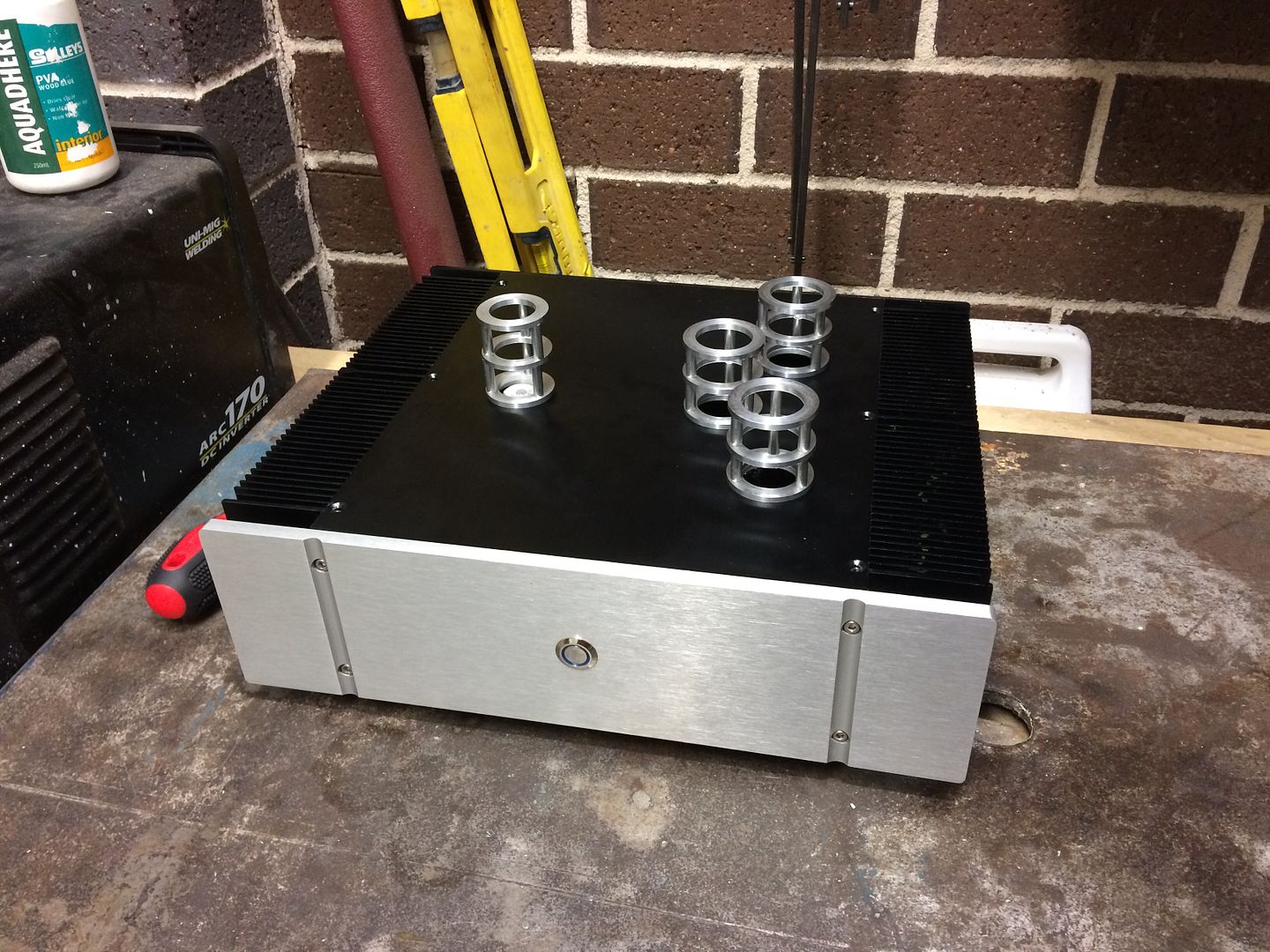
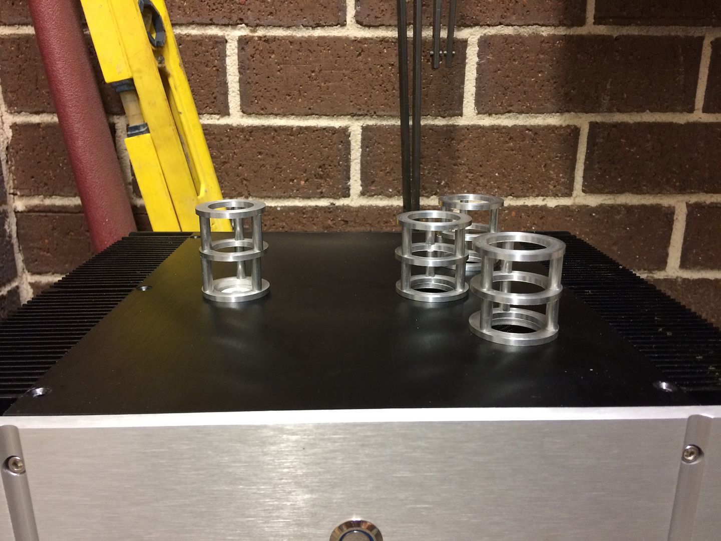
I had bought some M4 bolts to build it all tonight but the heads will be larger than the ring by a fraction and that will bug me. So I'll be getting some M3 instead so it meant I couldn't build it tonight. But I could put them together to see if I liked the look:
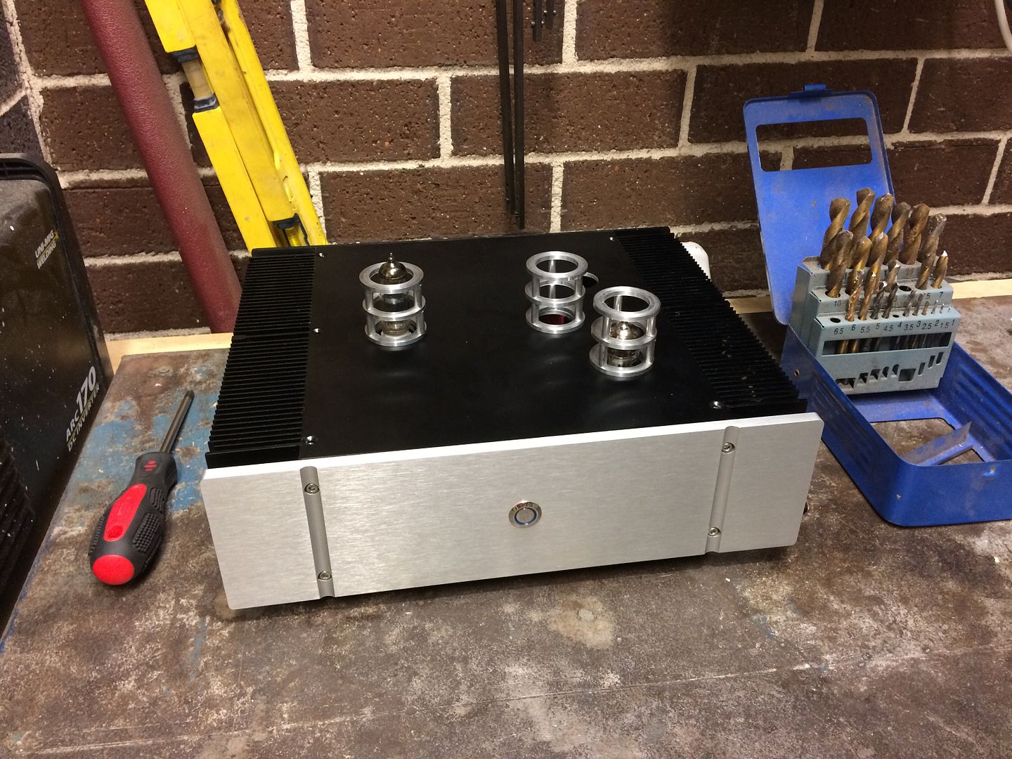
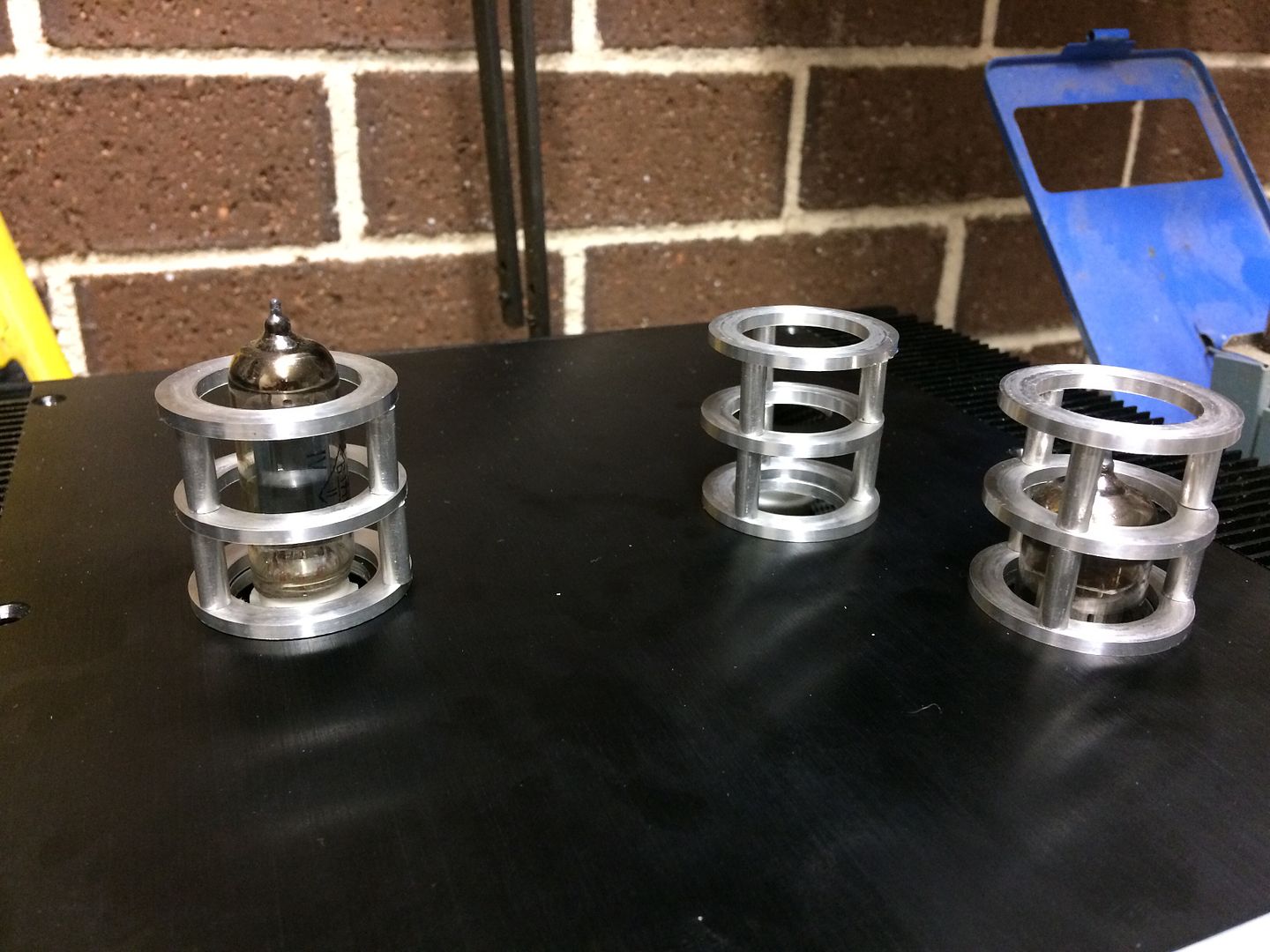
As I mentioned the rectifier one hasn't been made yet as I want match the guard to the tube so this one is here for looks only.
Needless to say I'm very pleased. I think it looks brilliant. Not sure if it helps but these guards will be earthed through the chassis too.
Here she is in all her glory:
I've also extended the tube sockets so I can get them flush with the lid of the chassis:
These ones will still have extra tube sockets too however as I couldn't find a tube socket for the 7 pin rectifier tube, I used 1.6mm TIG welding rod which is super sturdy. I'm also playing with the idea of using the old Alu tube covers for covering the sockets and the extensions to reduce the risk of noise.
I also redid the Alu sheild as I wanted it tidier and also the new RCA cable meant I could route it much easier:
The other thing I had been toying with was making some tube guards. Now the tubes will extend out the top of the chassis they are very vulnerable and guards would protect them, plus I was hoping they would help with the look on top as it was looking a little sparse even when the tubes were in.
The auction site had some nice ones but for all 4 it would run me approx $50, so I bought some Alu stock instead and set about making my own. This way I could make them exactly the right size and I could make them thicker too as I prefer the look.
First up with making the rings:
All done (only 3 sets so far as I'm going to make the rectifier the correct dimension too vs using 4 of the same):
Next up I used the lathe to trim the tube down to 15mm which had the rings in the right spot to cover the bottom/top of the tube, plus not cover the heater so I still get the glow. Rings and tube:
I had bought some M4 bolts to build it all tonight but the heads will be larger than the ring by a fraction and that will bug me. So I'll be getting some M3 instead so it meant I couldn't build it tonight. But I could put them together to see if I liked the look:
As I mentioned the rectifier one hasn't been made yet as I want match the guard to the tube so this one is here for looks only.
Needless to say I'm very pleased. I think it looks brilliant. Not sure if it helps but these guards will be earthed through the chassis too.
Thin wire will not be a problem. People often use wire that's far thicker than necessary and it causes more problems than it solves. Actually, there are no problems to solve.I've replaced the RCA cable and it's much thinner and easier to route in the amp. Hopefully the wire is ok for signal as its thin, but it's supposed to be good for 30V so I hope it's all ok.
You've done a great job - being able to use a lathe and making your own tube guards is very impressive.
BTW, you really should have a go at point-to-point-wiring. It's not that difficult and I'm sure you would make a very neat job of it. The only thing to bear in mind is that a lot of modern components (capacitors, mostly) are tiny and designed for PCB mounting and they're not ideally suited to P2P wiring, so select components accordingly.