About two years ago I picked up this amp, it was playing when I bought it at a ham radio fest.
The thing has had a rough life physically but it played fine.
The other day I turned it on and all was as usual but after about 20 minutes the left channel started to make some static. Then the right side started as well. I shut it down, checked all my connections and fired it back up.
It played fine for a few minutes then 'POP' and the left channel went out, the right side still plays but it makes some light static.
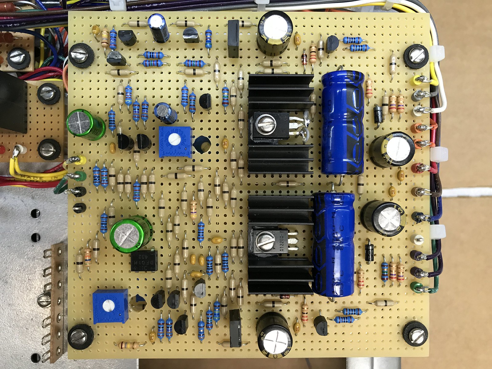
I pulled the cover off and found a blown fuse, and an obviously burnt 6.25K resistor.
I downloaded some info online for an LSR&D 101, including a schematic and parts list but nothing matches at all?
I took this to a local repair shop and they said its missing a lot of parts and can't be fixed???
I can see where there were two power transistors at one time, but they were never there all this time?
I only found one pic of another one with the top off online, and it doesn't match mine, all of the transistors are different, even the smaller amplifier transistors are diffferent.
From what i can tell this is an early model, from Feb 1979. It still uses the huge brick size e core transformer.
According to the parts list this should have 8) MJ15003, and 8) MJ15004 power transistors per channel, I have a hodge podge of various other part numbers that as far as i can tell do not cross over to the original part numbers.
As this was found, and how its been playing for the better part of two years its only had 14 power transistors installed?
The left channel has mostly Toshiba 2SB554 & 2SD424 power transistors installed, with an ECG87 and an ECG88, while the right channel has a mix of various Motorola MJ15011, MJ15012, MJ15024, and MJ15025 power transistors.
To make it more confusing, not a single other transistor, or 1/4 watt resistor on the board now is an option on the original parts list?
I'm thinking that I may need to start by replacing all the transistors with the correct part numbers or suitable audio grade equivalents? Not having dealt with one of these before I'm not sure how far they strayed from the original parts list when new either. There's no doubt parts have been changed but it did play, and it sounded pretty decent. How on earth it did missing two transistors is beyond me. I see no added jumpers or bridged circuits that would indicate something was modified so it didn't need the two other transistors but both are missing from the left channel circuit, which is also the channel which burnt the resistor. However, the fuse that popped was on the right channel?
The thing has had a rough life physically but it played fine.
The other day I turned it on and all was as usual but after about 20 minutes the left channel started to make some static. Then the right side started as well. I shut it down, checked all my connections and fired it back up.
It played fine for a few minutes then 'POP' and the left channel went out, the right side still plays but it makes some light static.
I pulled the cover off and found a blown fuse, and an obviously burnt 6.25K resistor.
I downloaded some info online for an LSR&D 101, including a schematic and parts list but nothing matches at all?
I took this to a local repair shop and they said its missing a lot of parts and can't be fixed???
I can see where there were two power transistors at one time, but they were never there all this time?
I only found one pic of another one with the top off online, and it doesn't match mine, all of the transistors are different, even the smaller amplifier transistors are diffferent.
From what i can tell this is an early model, from Feb 1979. It still uses the huge brick size e core transformer.
According to the parts list this should have 8) MJ15003, and 8) MJ15004 power transistors per channel, I have a hodge podge of various other part numbers that as far as i can tell do not cross over to the original part numbers.
As this was found, and how its been playing for the better part of two years its only had 14 power transistors installed?
The left channel has mostly Toshiba 2SB554 & 2SD424 power transistors installed, with an ECG87 and an ECG88, while the right channel has a mix of various Motorola MJ15011, MJ15012, MJ15024, and MJ15025 power transistors.
To make it more confusing, not a single other transistor, or 1/4 watt resistor on the board now is an option on the original parts list?
I'm thinking that I may need to start by replacing all the transistors with the correct part numbers or suitable audio grade equivalents? Not having dealt with one of these before I'm not sure how far they strayed from the original parts list when new either. There's no doubt parts have been changed but it did play, and it sounded pretty decent. How on earth it did missing two transistors is beyond me. I see no added jumpers or bridged circuits that would indicate something was modified so it didn't need the two other transistors but both are missing from the left channel circuit, which is also the channel which burnt the resistor. However, the fuse that popped was on the right channel?