

Cut-Throat
Well-Known Member
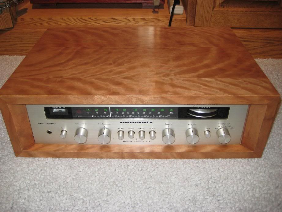
I got a Marantz 26 Receiver that was not working in one channel last winter. I have completely refurbed it. Replaced all electrolytic Caps, LED lights, had the one channel fixed, Auricaps in the signal Path. I also had Dan Crosby (forum Member) build me a Custom Curly Cherry Cabinet. I have over $500 in this receiver and it is only worth it to me. So I will keep it forever. It is the smallest receiver that Marantz ever made. It is tiny. I'll attach before and after pics of re-capping and tips for anyone that may want to re-cap a Solid State Receiver.
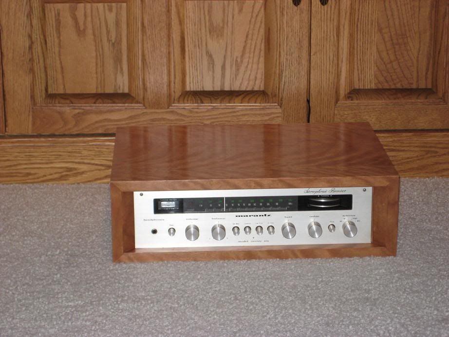
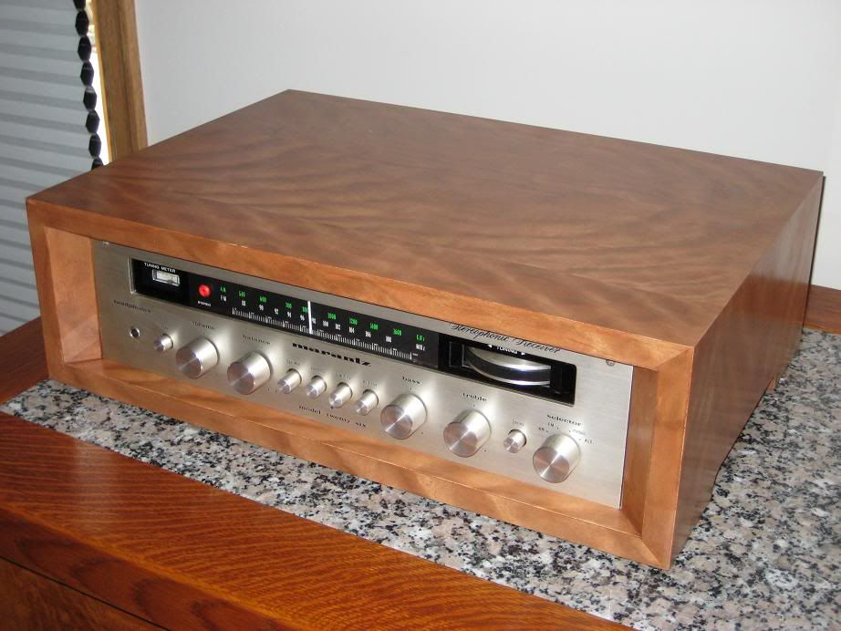
Completed Receiver.
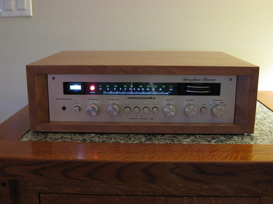
Lit Up and Running.
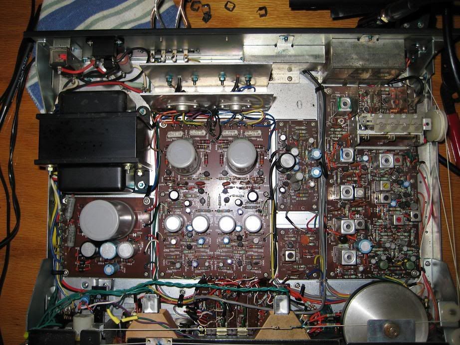
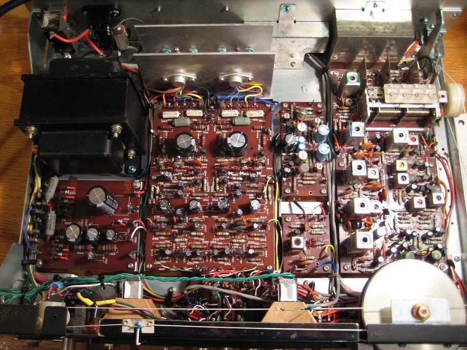
Well, I succeeded in successfully re-capping this little Marantz 26 Receiver! The re-capping improved the sound immensely! - It's like this dull receiver came to life! - It sounds really super now ! I have got before and after pictures. Notice how large the Vintage Electrolytic Caps in the Power Supply are compared to the new caps.
Before
After Re-Cap
I do have some tips that are 'fresh' in my mind for re-capping a receiver.
The hardest thing about this project was finding the right solder joints on the back of the board. Sometimes I would have to unsolder a couple joints, before I hit the right one. So the biggest tip is unsolder the joint that you think might be one. Then wiggle the cap from the other side and see if the little wire sticking through is your intended cap. If it moves you'll know you hit the right one and it will tell you where the other leg is.
1.) Remove the top and bottom covers from the receiver and stand it on it's edge, with the board you are working on towards the top. I also removed the faceplate and knobs to keep from scratching them. Do not remove any of the PCB boards, if you can easily get to the rear of the board where the solder joints are. I did not have to remove any of the boards on this Marantz Model 26.
2.) Hook a pair of small cheap speakers to the receiver and an antenna to pull in an FM station, so that you can test it as you go. Make sure that this all works before you start.
3.) What also worked great for me, is to have the receiver plugged into a Power Strip so that I could flip the switch of the Power Strip off and on for testing, and that kept all the voltage off the receiver and I did not have to keep unplugging it. I never use the switch of the receiver, because this would still leave voltage on the back of the receiver and I don't like to wear out vintage switches. I use the surge strip even when they are done and in my system.
4.) Mark each cap with a sharpie showing its position on the board. IOW - I made a small arrow towards the front of the receiver. Then when the cap is removed you'll know for sure the position of the cap polarity. Don't trust the + or - on the board as they can be wrong sometimes. Don't trust the parts list in the service manual either, as I found mistakes in mine. Look at the markings on the cap for uf and Voltage. Double check before replacing each one. Short lead of the new radial is negative and is usually marked with an arrow.
5.) Replace the largest caps on the PCB board you are working on first. The new caps will be smaller and you will make more working room for your fingers, so that the smaller caps will be easier to see, wiggle and pull out.
6.) When unsoldering the legs of the old cap, I used small solder braid about 1/8 inch. Hold the tip of the soldering iron to the solder joint with the braid and suck up most all the solder until it reveals the bent tip of the old cap leg. The solder will still hold the leg to the trace. Don't try to lift it without applying heat otherwise it will lift the trace. Take a very small knife or scalpel and at the same time when applying the solder tip for heat, slide the scalpel under the leg and it will straighten out nicely and be free of solder. Then wiggle the cap from the other side and make sure you have the correct leg of the cap you are trying to unsolder. If it wiggles you'll be able to tell when the other leg is. Repeat on the other leg and then you should be able to pull the old cap out.
7) Double check the value of the old cap and replace with new on, being sure to check for polarity. Short lead is negative. If you forget look at the old cap and line up the arrow you drew on top so that it points to the front of the receiver and check its polarity position. Remember when you do the PCB boards towards the other end of the receiver, you'll flip the receiver over for easier access of the solder joints. The front of the receiver will now be pointing the other direction. So will the polarity position of the caps. Just make sure which is the front of the receiver.
8.) After the new cap is inserted correctly into the holes. With one hand Push the cap flush to the board. With the other hand using a very small screwdriver bend over the wires of the new cap and push them with the screwdriver flush to the board, until the cap is firmly attached. Then solder in place. Lift the extra wires remaining on the leg and trim with a tiny pair of wire cutters. I bought an electrical pair. Trying to use a full size wire cutter is frustrating, because you cannot get it close enough to the solder joint. My little wire cutter has sharp blades and a tiny point and I could trim the wire flush to the solder joint.
9.) I did one PCB board at a time keeping the board that I am working on towards the top of the receiver. After 1 or 2 caps I always turned on the receiver to make sure it was functioning. That way if it didn't work, I knew which cap that was incorrect. I always turned my head when I flipped on the power in case I had the polarity wrong. - Luckily I did not make one mistake. After flipping the power off, use your multimeter to make sure the caps are fully discharged before starting on another one. My caps fully drained after about 30 seconds with the power off.
10.) Work slowly. I only did about 4 or 5 caps at a sitting. Don't try and rush the project, you'll do a better job and make fewer mistakes. It will all be done in a few days anyway!
Completed Receiver.
Lit Up and Running.
Well, I succeeded in successfully re-capping this little Marantz 26 Receiver! The re-capping improved the sound immensely! - It's like this dull receiver came to life! - It sounds really super now ! I have got before and after pictures. Notice how large the Vintage Electrolytic Caps in the Power Supply are compared to the new caps.
Before
After Re-Cap
I do have some tips that are 'fresh' in my mind for re-capping a receiver.
The hardest thing about this project was finding the right solder joints on the back of the board. Sometimes I would have to unsolder a couple joints, before I hit the right one. So the biggest tip is unsolder the joint that you think might be one. Then wiggle the cap from the other side and see if the little wire sticking through is your intended cap. If it moves you'll know you hit the right one and it will tell you where the other leg is.
1.) Remove the top and bottom covers from the receiver and stand it on it's edge, with the board you are working on towards the top. I also removed the faceplate and knobs to keep from scratching them. Do not remove any of the PCB boards, if you can easily get to the rear of the board where the solder joints are. I did not have to remove any of the boards on this Marantz Model 26.
2.) Hook a pair of small cheap speakers to the receiver and an antenna to pull in an FM station, so that you can test it as you go. Make sure that this all works before you start.
3.) What also worked great for me, is to have the receiver plugged into a Power Strip so that I could flip the switch of the Power Strip off and on for testing, and that kept all the voltage off the receiver and I did not have to keep unplugging it. I never use the switch of the receiver, because this would still leave voltage on the back of the receiver and I don't like to wear out vintage switches. I use the surge strip even when they are done and in my system.
4.) Mark each cap with a sharpie showing its position on the board. IOW - I made a small arrow towards the front of the receiver. Then when the cap is removed you'll know for sure the position of the cap polarity. Don't trust the + or - on the board as they can be wrong sometimes. Don't trust the parts list in the service manual either, as I found mistakes in mine. Look at the markings on the cap for uf and Voltage. Double check before replacing each one. Short lead of the new radial is negative and is usually marked with an arrow.
5.) Replace the largest caps on the PCB board you are working on first. The new caps will be smaller and you will make more working room for your fingers, so that the smaller caps will be easier to see, wiggle and pull out.
6.) When unsoldering the legs of the old cap, I used small solder braid about 1/8 inch. Hold the tip of the soldering iron to the solder joint with the braid and suck up most all the solder until it reveals the bent tip of the old cap leg. The solder will still hold the leg to the trace. Don't try to lift it without applying heat otherwise it will lift the trace. Take a very small knife or scalpel and at the same time when applying the solder tip for heat, slide the scalpel under the leg and it will straighten out nicely and be free of solder. Then wiggle the cap from the other side and make sure you have the correct leg of the cap you are trying to unsolder. If it wiggles you'll be able to tell when the other leg is. Repeat on the other leg and then you should be able to pull the old cap out.
7) Double check the value of the old cap and replace with new on, being sure to check for polarity. Short lead is negative. If you forget look at the old cap and line up the arrow you drew on top so that it points to the front of the receiver and check its polarity position. Remember when you do the PCB boards towards the other end of the receiver, you'll flip the receiver over for easier access of the solder joints. The front of the receiver will now be pointing the other direction. So will the polarity position of the caps. Just make sure which is the front of the receiver.
8.) After the new cap is inserted correctly into the holes. With one hand Push the cap flush to the board. With the other hand using a very small screwdriver bend over the wires of the new cap and push them with the screwdriver flush to the board, until the cap is firmly attached. Then solder in place. Lift the extra wires remaining on the leg and trim with a tiny pair of wire cutters. I bought an electrical pair. Trying to use a full size wire cutter is frustrating, because you cannot get it close enough to the solder joint. My little wire cutter has sharp blades and a tiny point and I could trim the wire flush to the solder joint.
9.) I did one PCB board at a time keeping the board that I am working on towards the top of the receiver. After 1 or 2 caps I always turned on the receiver to make sure it was functioning. That way if it didn't work, I knew which cap that was incorrect. I always turned my head when I flipped on the power in case I had the polarity wrong. - Luckily I did not make one mistake. After flipping the power off, use your multimeter to make sure the caps are fully discharged before starting on another one. My caps fully drained after about 30 seconds with the power off.
10.) Work slowly. I only did about 4 or 5 caps at a sitting. Don't try and rush the project, you'll do a better job and make fewer mistakes. It will all be done in a few days anyway!
Last edited:
