

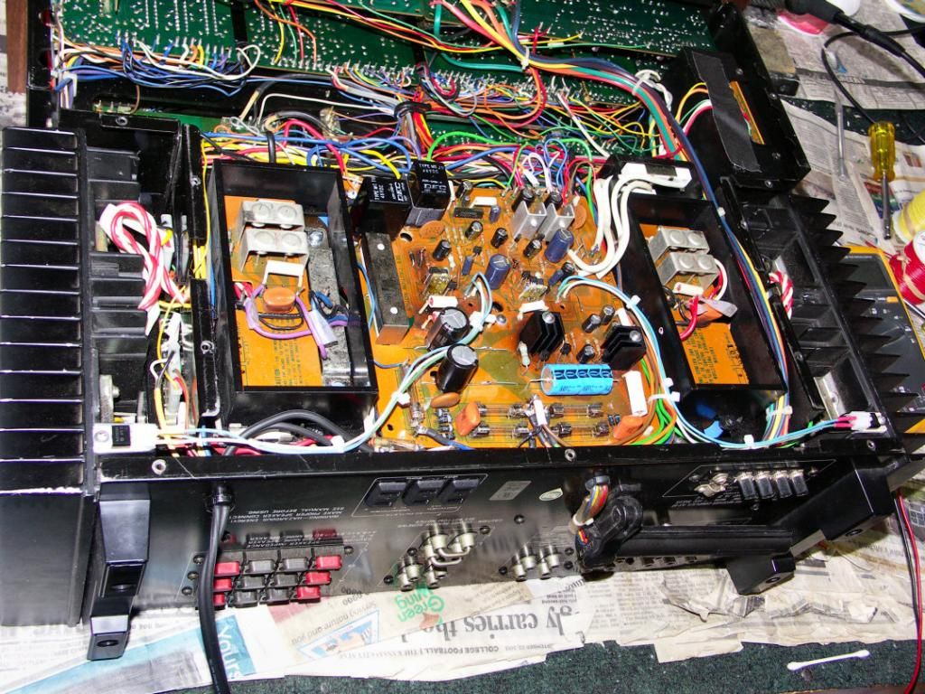
Everyone knows these get stupid hot. I suggested in another thread moving both the TO-220 pass transistors for the +/-80V supply to the big output transistor heatsinks.
So I did.
Closeup of one...
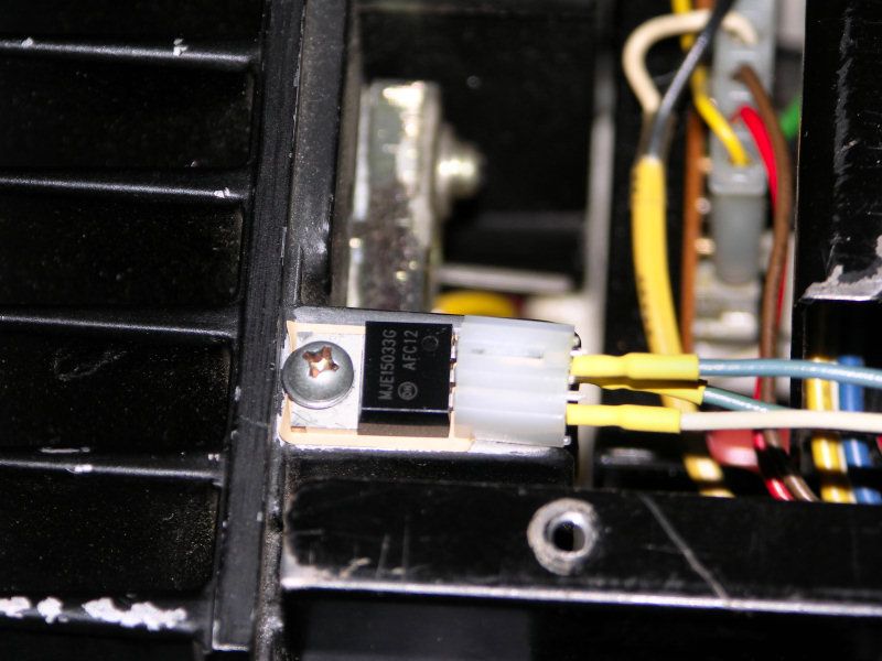
I used the MJE15032G and 33G for this experiment. I wanted to use the insulated MJF15030 and MJF15031, but no one has the '30. I have some ordered but delivery won't be till February or later. So, for insulation, Mouser has TO-220 shoulder washers and Bergquist thermal pads (or you can use mica and heatsink grease).
On the big 1980 heatsinks, there's some holes at the mounting location, but they are too large and too close to the edge of the heatsink. I drilled new holes in a location which allowed for proper mounting (#39 bit, 0.099") and used a standard 2.9mm x 13mm metric sheet metal screw and a 3mm flat washer with the shoulder washer to isolate the screw.
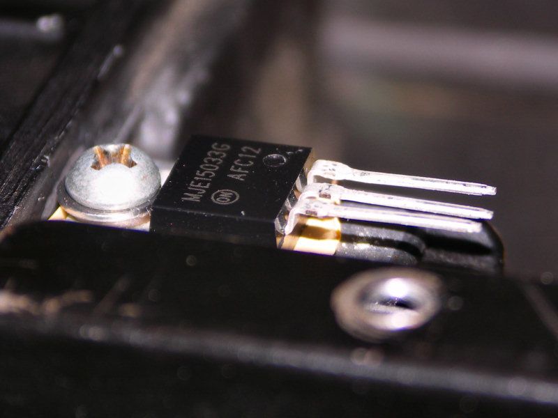
I wanted to be able to disconnect the transistors easily, so I used some Molex TO-220 sockets. These are seriously nice sockets and grip the transistor very well. Only complaint is their 'height', in that the leads of the transistor have to be bent up and then back to allow clearance (pic below). Used 20ga wire to wire 'em up, but the current is low and even 24ga would be fine.
Clearance from the TO-220 socket and the bottom panel is, well, more than tight. The bottom panel just misses the plastic connector by a mm or two, but all conductors are recessed so shorting is not an issue. But I may cover a small section of the bottom panel with a piece of insulating tape to make me feel better.
Q203 (13.5V supply) and Q205 (8V and 5V) still get rather warm, but their heatsinks were changed to some 1" tall jobs that are much nicer than the originals. That, and with the 80V transistors located remotely, I can't think of a reason to leave the big heatsink in place. Q203 still gets damn hot, but it's an improvement and with the removal of the big heatsink airflow has to be better (poor still, I'm sure, but better than before). The original was held on with a screw from underneath the board, so I used a #4-40 x 1 3/8" machine screw and a few washers (on top and underneath) with a nut and lockwasher to secure the new heatsinks (bought locally, no part numbers).
Parts:
HS300-ND Digikey 25.4mm x 16mm TO-220 heatsink
532-7721-8PPS Mouser TO-220 shoulder washer (necessary if using collector tab TO-220's)
94997A275 McMaster-Carr 2.9mm x 13mm sheet metal screw #1 philips drive
93475A210 McMaster-Carr 3mm stainless flat washer
WM2550-ND Digikey Molex TO-220 socket.
22ga stranded hook-up wire (recommended)
The big output heatsinks show no perceptible rise in temp, and the two +/-80V pass transistors are cool as a cucumber.
So I did.
Closeup of one...
I used the MJE15032G and 33G for this experiment. I wanted to use the insulated MJF15030 and MJF15031, but no one has the '30. I have some ordered but delivery won't be till February or later. So, for insulation, Mouser has TO-220 shoulder washers and Bergquist thermal pads (or you can use mica and heatsink grease).
On the big 1980 heatsinks, there's some holes at the mounting location, but they are too large and too close to the edge of the heatsink. I drilled new holes in a location which allowed for proper mounting (#39 bit, 0.099") and used a standard 2.9mm x 13mm metric sheet metal screw and a 3mm flat washer with the shoulder washer to isolate the screw.
I wanted to be able to disconnect the transistors easily, so I used some Molex TO-220 sockets. These are seriously nice sockets and grip the transistor very well. Only complaint is their 'height', in that the leads of the transistor have to be bent up and then back to allow clearance (pic below). Used 20ga wire to wire 'em up, but the current is low and even 24ga would be fine.
Clearance from the TO-220 socket and the bottom panel is, well, more than tight. The bottom panel just misses the plastic connector by a mm or two, but all conductors are recessed so shorting is not an issue. But I may cover a small section of the bottom panel with a piece of insulating tape to make me feel better.
Q203 (13.5V supply) and Q205 (8V and 5V) still get rather warm, but their heatsinks were changed to some 1" tall jobs that are much nicer than the originals. That, and with the 80V transistors located remotely, I can't think of a reason to leave the big heatsink in place. Q203 still gets damn hot, but it's an improvement and with the removal of the big heatsink airflow has to be better (poor still, I'm sure, but better than before). The original was held on with a screw from underneath the board, so I used a #4-40 x 1 3/8" machine screw and a few washers (on top and underneath) with a nut and lockwasher to secure the new heatsinks (bought locally, no part numbers).
Parts:
HS300-ND Digikey 25.4mm x 16mm TO-220 heatsink
532-7721-8PPS Mouser TO-220 shoulder washer (necessary if using collector tab TO-220's)
94997A275 McMaster-Carr 2.9mm x 13mm sheet metal screw #1 philips drive
93475A210 McMaster-Carr 3mm stainless flat washer
WM2550-ND Digikey Molex TO-220 socket.
22ga stranded hook-up wire (recommended)
The big output heatsinks show no perceptible rise in temp, and the two +/-80V pass transistors are cool as a cucumber.
Last edited:
") Great idea!
Great idea!