

Hello friends of the good old Pioneer receivers,
I’m writing you from Germany and hope for some help and ideas for my rebuild of my first SX-828.
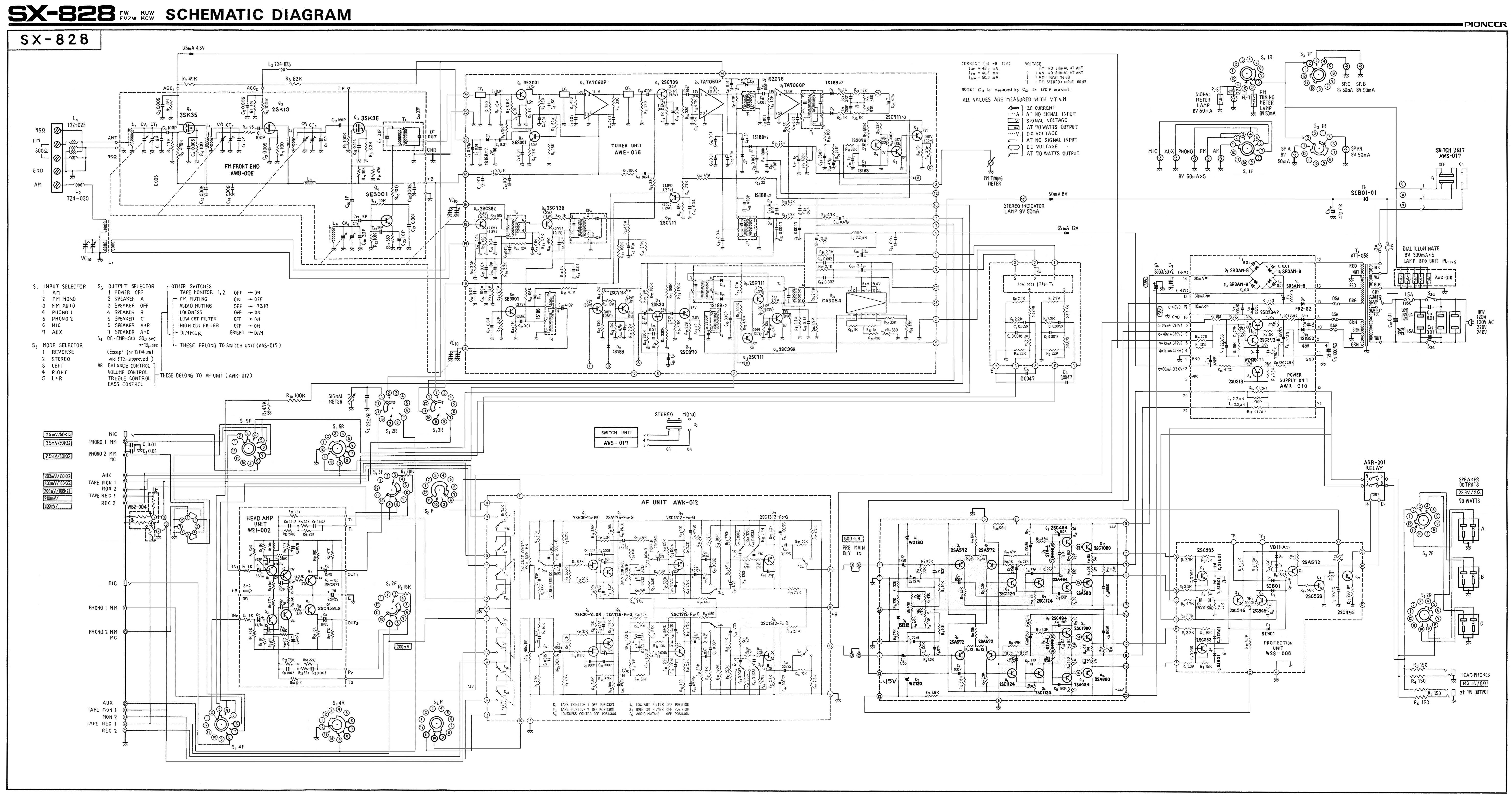
Actually I have cleaned the interior and want to start with the work on the power supply board, followed by the protection and the head amp unit.
As a first thing I measured the voltage on all pins of the Power supply unit AWR-010 and was wondering which AC-voltage will come out of the Transformer ATT-059.
The Voltage from the wallsocket is 238V here in Germany, the selector on the SX-828 is set to 240V.
I got the following AC-Values.
PIN 8 = 29 VAC,
PIN 9 = 35 VAC
PIN 10 = 30 VAC
PIN 12 and 13 = 24 VAC
PIN 18 = 28.8 VAC
Are these OK??
On the DC site, I had some strange values.
PIN 2 = 12 VDC, that seems OK
PIN 4 = 4.4
PIN 5 = 31.7
PIN 6 = 29.9
PIN 7 = 31.7
PIN 9 = 35V should be 49V
PIN 14 = 30.4 V should be 44V
PIN 15 = -30.4 V should be -44V
PIN 17 = -29.9 V should be -45V
I will change all caps, the 3 transistors with new ones and change the R12 (330 Ohm 2W) with a 330 Ohm 3W to reduce the heat in that area.
BUT what can be the cause for the low voltages on the pins 9 – 14 – 15 and 17?
Any idea where else I should look at to get the correct voltage on that pins?
I’m writing you from Germany and hope for some help and ideas for my rebuild of my first SX-828.
Actually I have cleaned the interior and want to start with the work on the power supply board, followed by the protection and the head amp unit.
As a first thing I measured the voltage on all pins of the Power supply unit AWR-010 and was wondering which AC-voltage will come out of the Transformer ATT-059.
The Voltage from the wallsocket is 238V here in Germany, the selector on the SX-828 is set to 240V.
I got the following AC-Values.
PIN 8 = 29 VAC,
PIN 9 = 35 VAC
PIN 10 = 30 VAC
PIN 12 and 13 = 24 VAC
PIN 18 = 28.8 VAC
Are these OK??
On the DC site, I had some strange values.
PIN 2 = 12 VDC, that seems OK
PIN 4 = 4.4
PIN 5 = 31.7
PIN 6 = 29.9
PIN 7 = 31.7
PIN 9 = 35V should be 49V
PIN 14 = 30.4 V should be 44V
PIN 15 = -30.4 V should be -44V
PIN 17 = -29.9 V should be -45V
I will change all caps, the 3 transistors with new ones and change the R12 (330 Ohm 2W) with a 330 Ohm 3W to reduce the heat in that area.
BUT what can be the cause for the low voltages on the pins 9 – 14 – 15 and 17?
Any idea where else I should look at to get the correct voltage on that pins?


 I didn't notice any "special notations" for the different revisions here so it appears all board level voltages/values should be the same. Any "exception" would be any possible later in-production component or board revisions not shown here.
")