

You are using an out of date browser. It may not display this or other websites correctly.
You should upgrade or use an alternative browser.
You should upgrade or use an alternative browser.
Recap parts list for an MX-110 Z??
- Thread starter scootchu
- Start date

analog addict
Glory or Death!
New caps are in....
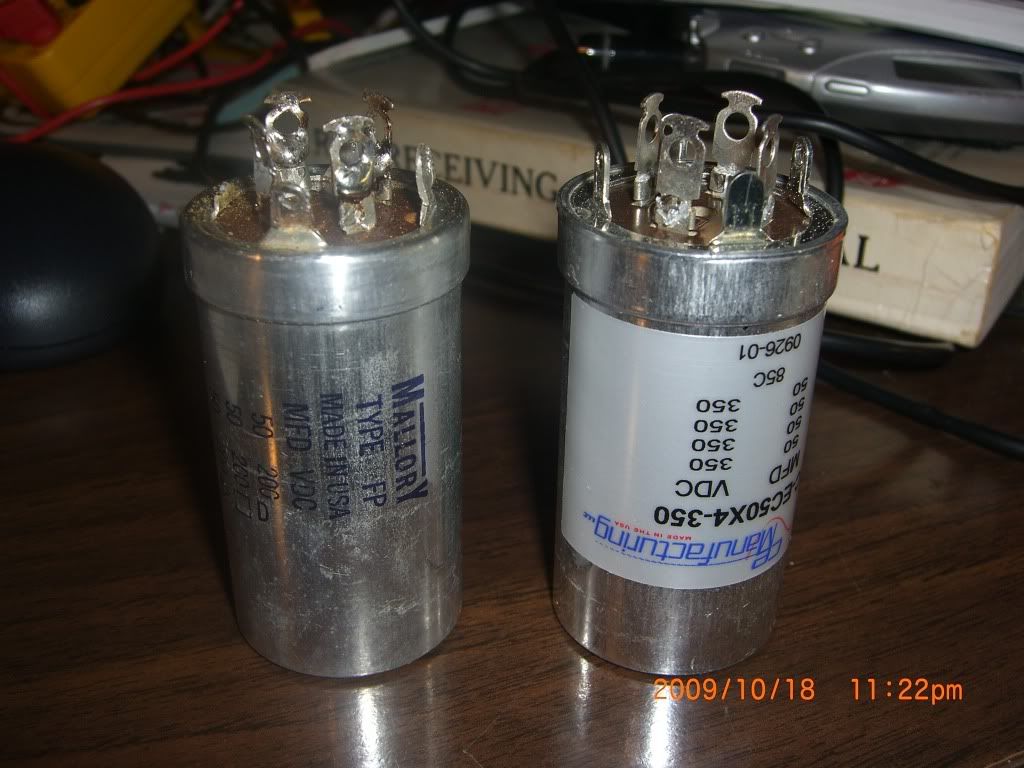
Got one of them in, I'll do the other tomorrow if my day winds up only 12 or so hours. If it stretches to 14 or longer, it'll have to wait a few....
Before and after pix when finished. Also eyeing the selenium rectifiers.....:scratch2:
Got one of them in, I'll do the other tomorrow if my day winds up only 12 or so hours. If it stretches to 14 or longer, it'll have to wait a few....
Before and after pix when finished. Also eyeing the selenium rectifiers.....:scratch2:
analog addict
Glory or Death!
Cans are in....
Now I just need to figger out the wiring for the Full Bridge rectifier, and how to do the current inrush limiter....
Doe it matter that the one 70uF section is now going to be 100uF with tying together 2 of the 50uF sections on the new can?
Getting close....:yes:
Now I just need to figger out the wiring for the Full Bridge rectifier, and how to do the current inrush limiter....
Doe it matter that the one 70uF section is now going to be 100uF with tying together 2 of the 50uF sections on the new can?
Getting close....:yes:
analog addict
Glory or Death!
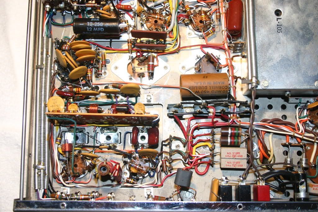
Took a look at my other MX-110Z...
...that dshoaf restored....
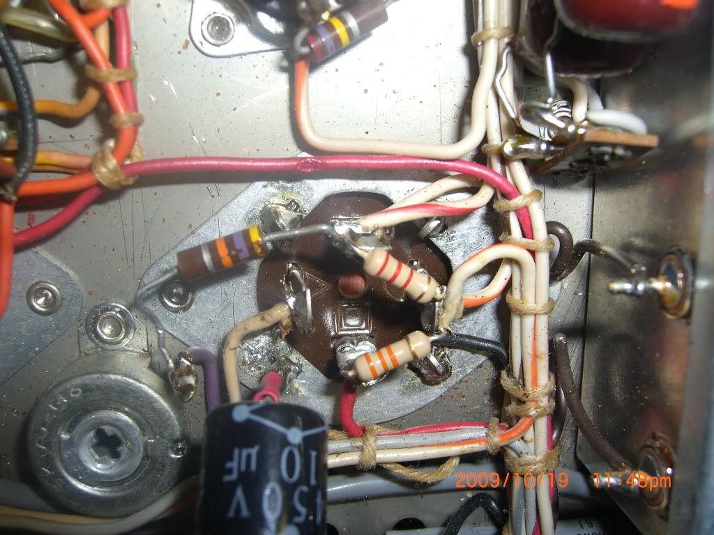
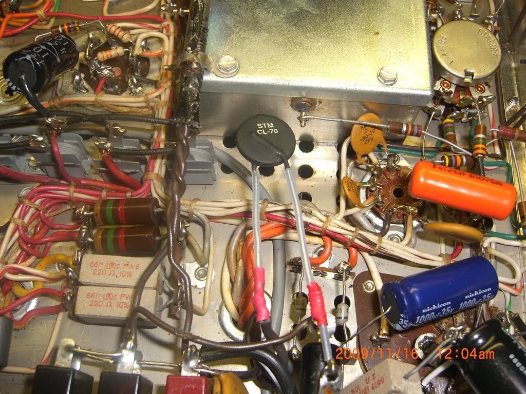
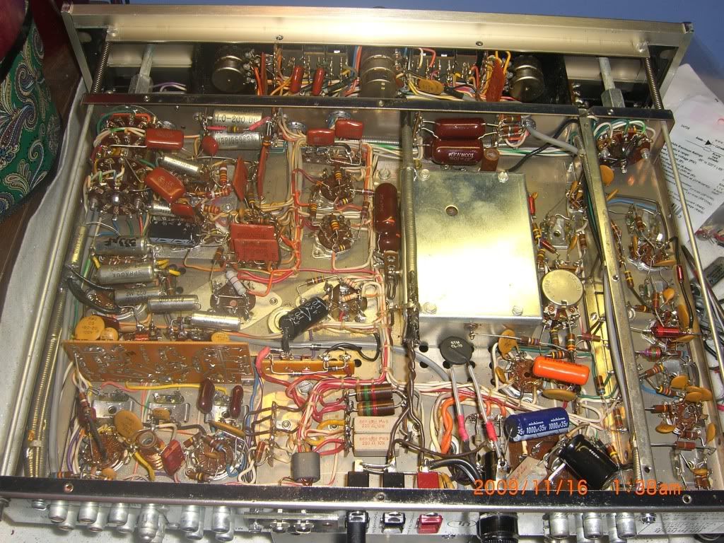
Here's the placement of the thermistor. I'm going to replace the two diodes D-15 and D-16 visible underneath (1N1217's) with 1N4005's or 6's. Apparently they are part of the filament supply...
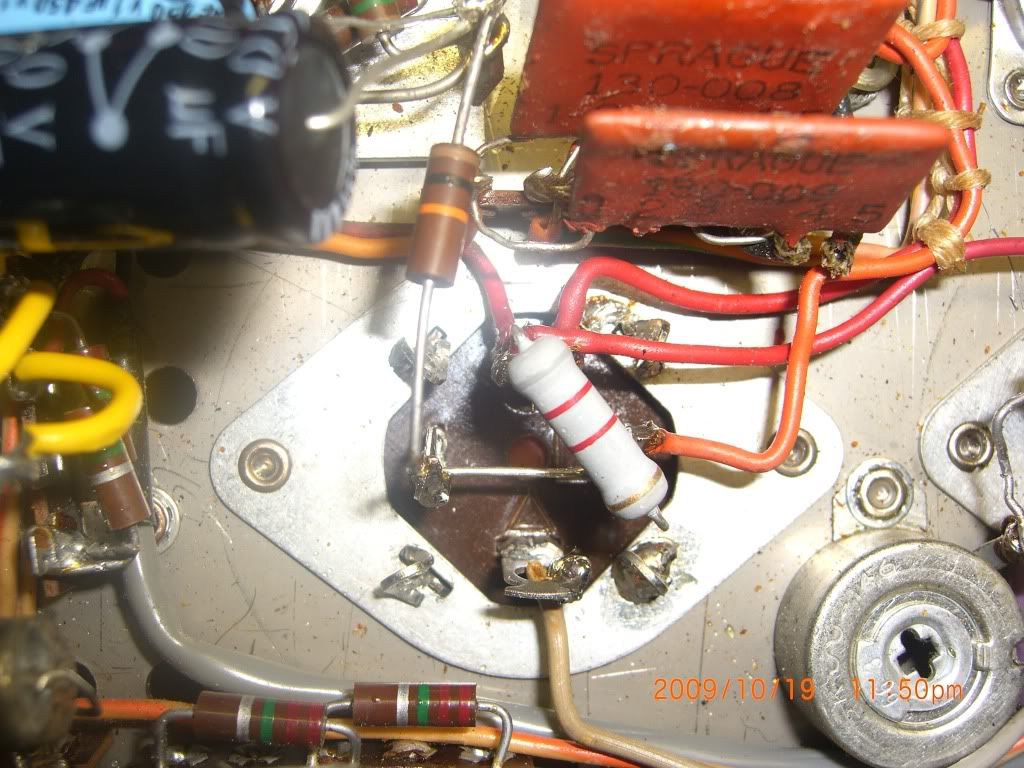
And here's the rectifier....Looks like a prepackaged full bridge instead of a 1N4007 set up....
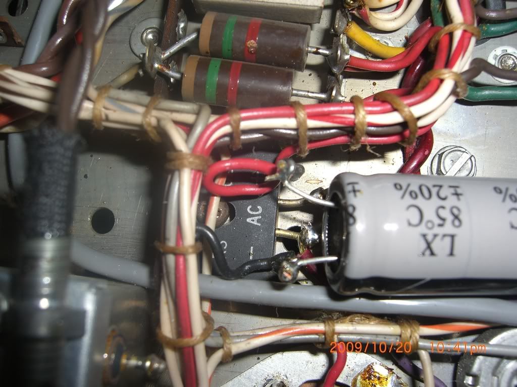
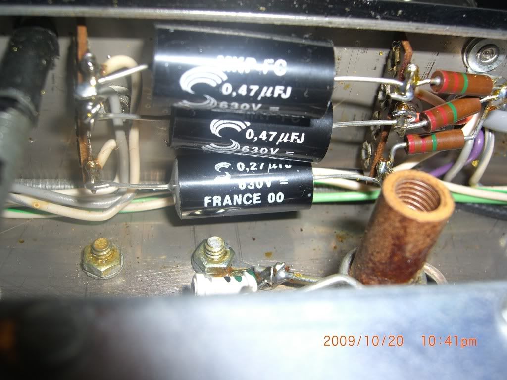
Looks like some of the dog bone 0.47's were done. Solens here, but I have a bunch of Vit Q's that I think I will throw in while I'm underneath....:scratch2:
...that dshoaf restored....
Here's the placement of the thermistor. I'm going to replace the two diodes D-15 and D-16 visible underneath (1N1217's) with 1N4005's or 6's. Apparently they are part of the filament supply...
And here's the rectifier....Looks like a prepackaged full bridge instead of a 1N4007 set up....
Looks like some of the dog bone 0.47's were done. Solens here, but I have a bunch of Vit Q's that I think I will throw in while I'm underneath....:scratch2:
Last edited:
dshoaf
That high voltage buzz
Some additional notes on AA's pictures:
- Yeah, I did that one before I discovered the brown/'dog bone' caps didn't need the attention I gave them. The Solens actually, IMHO, do quite well in this preamp section. They're really easy to swap out, too.
- That's a 1000 PIV bridge rectifier in there replacing the original 4 selenium diodes.
- On swapping the 2 diodes in the filament circuit - those 2 little white ones in the pics: Be careful with the terminal strips as they tend to crack easily. I'd suggest cutting out the old components and resoldering new ones in rather than trying to removing all the solder and then manipulate the old ones out with leads intact.
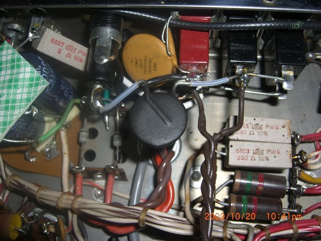
- The thermistor is installed on the AC input side of the transformer. The most convenient to place is in series with the power fuse in order for it to stand clear enough not to cook all the other components around it when it gets hot.
Cheers,
David
- Yeah, I did that one before I discovered the brown/'dog bone' caps didn't need the attention I gave them. The Solens actually, IMHO, do quite well in this preamp section. They're really easy to swap out, too.
- That's a 1000 PIV bridge rectifier in there replacing the original 4 selenium diodes.
- On swapping the 2 diodes in the filament circuit - those 2 little white ones in the pics: Be careful with the terminal strips as they tend to crack easily. I'd suggest cutting out the old components and resoldering new ones in rather than trying to removing all the solder and then manipulate the old ones out with leads intact.
- The thermistor is installed on the AC input side of the transformer. The most convenient to place is in series with the power fuse in order for it to stand clear enough not to cook all the other components around it when it gets hot.
Cheers,
David
analog addict
Glory or Death!
A little help please....
I'm having a hard time reconciling the bridge I think needs to go in here, and the actual circuit in front of me. Here's the bridge schematic....
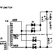
Correct em if I'm wrong, but this shows the 10 uF/450 cap connected to the cathodes of D11 and D12. Well, my 10 uF cap is clearly connected up to the positively marked terminal of the selenium stack, like in this picture from earlier in the thread...
Does the selenium rectifier work differently from Si based diodes?
I'm confused. Maybe I could beg a favor from Murray and see if he'd post a closeup picture of his bridge and the connections to it....:sigh:
EDIT: Now that I look at it, the red X-former leads are also soldered into the positive terminals of D13 and D14. So the polarity of these seleniums must somehow be reversed from Si diodes, no? So should I follow the schematic or the polarity of the current rectifier set up for the replacement diodes? (I think I know the answer, but I don't want any screw ups here...)
And Dave, I do have 5 of the 0.47 uF Vit Q's sitting around. Is there any appreciable sonic improvement to be had by subbing these in for all the 0.47 brown dog bones?
I'm having a hard time reconciling the bridge I think needs to go in here, and the actual circuit in front of me. Here's the bridge schematic....
Correct em if I'm wrong, but this shows the 10 uF/450 cap connected to the cathodes of D11 and D12. Well, my 10 uF cap is clearly connected up to the positively marked terminal of the selenium stack, like in this picture from earlier in the thread...
Does the selenium rectifier work differently from Si based diodes?
I'm confused. Maybe I could beg a favor from Murray and see if he'd post a closeup picture of his bridge and the connections to it....:sigh:
EDIT: Now that I look at it, the red X-former leads are also soldered into the positive terminals of D13 and D14. So the polarity of these seleniums must somehow be reversed from Si diodes, no? So should I follow the schematic or the polarity of the current rectifier set up for the replacement diodes? (I think I know the answer, but I don't want any screw ups here...)
And Dave, I do have 5 of the 0.47 uF Vit Q's sitting around. Is there any appreciable sonic improvement to be had by subbing these in for all the 0.47 brown dog bones?
Last edited:
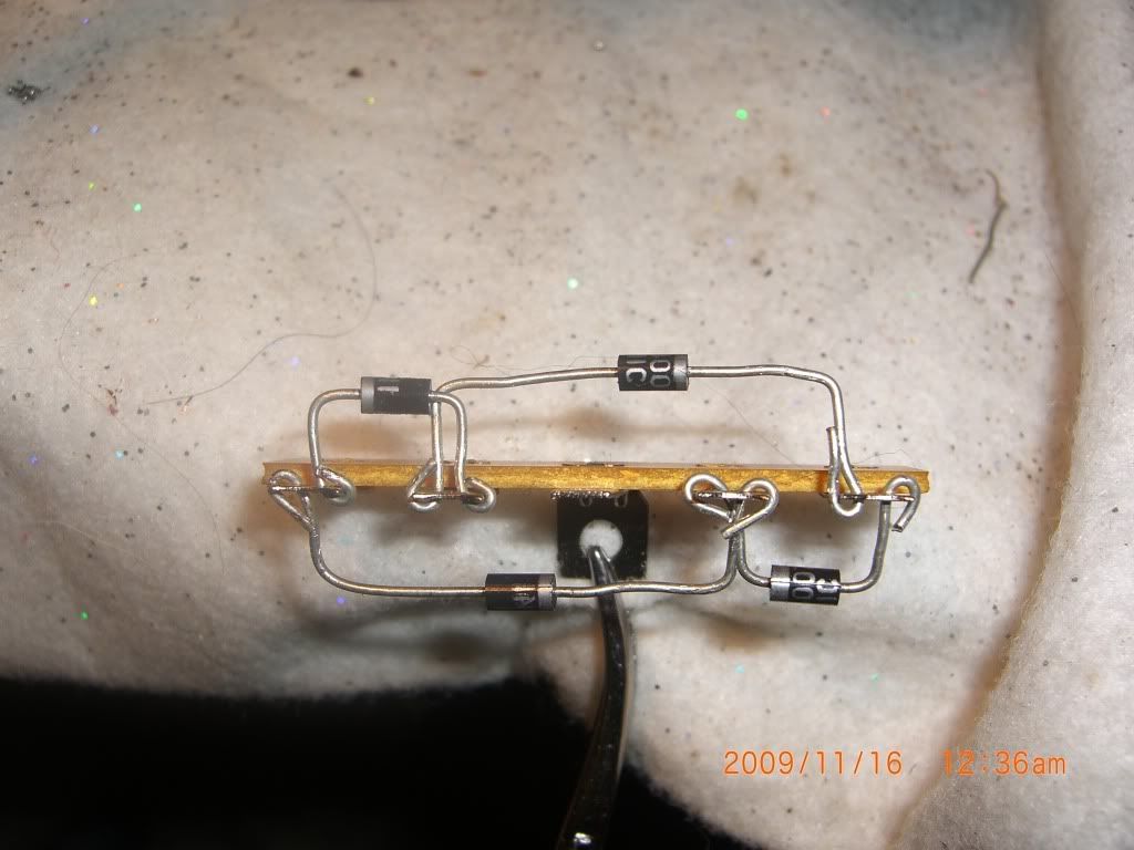
Here's a pic of the one that Wes fabricated. I just spent a couple of minutes looking at it but it seems to follow the general layout of the seleniums. Mine is the same except that I spent some time figuring out how to eliminate the jumper wires.
As you look across the diodes, you can see how the cathode is flipped relative to its neighbor, just like the seleniums appear to be.
Edit: I found another pic of mine, from the other direction.
Murray
As you look across the diodes, you can see how the cathode is flipped relative to its neighbor, just like the seleniums appear to be.
Edit: I found another pic of mine, from the other direction.
Murray
Attachments


Last edited:


analog addict
Glory or Death!
I think I'm finished....
Put the thermistor and the rectifier bridge in tonight. Wanted to see if anyone has any final thoughts if I did it right.
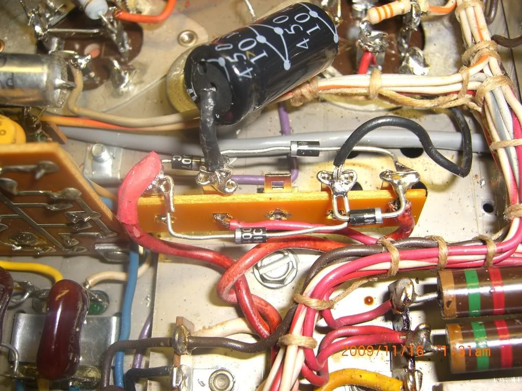
Here's the thermistor....
I've found old threads showing it wired in on both sides of the fuse. I wired it in directly between the collar of the fuse and the power transformer. I did this mainly so that I could position it right under the open vents.
Would this be equivalent to wiring it between the other terminal of the fuse and the AC outlet? Someone shout out if this is not right.....:nono:
Here's the configuration of the diode bridge....
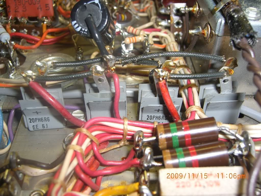
The original circuit with seleniums.....
and the bridge wired into place? Look OK?
Last but not least, the final product.....
I'm gonna wait until tomorrow and bring it up gradually on a variac.....:thmbsp:
Put the thermistor and the rectifier bridge in tonight. Wanted to see if anyone has any final thoughts if I did it right.
Here's the thermistor....
I've found old threads showing it wired in on both sides of the fuse. I wired it in directly between the collar of the fuse and the power transformer. I did this mainly so that I could position it right under the open vents.
Would this be equivalent to wiring it between the other terminal of the fuse and the AC outlet? Someone shout out if this is not right.....:nono:
Here's the configuration of the diode bridge....
The original circuit with seleniums.....
and the bridge wired into place? Look OK?
Last but not least, the final product.....
I'm gonna wait until tomorrow and bring it up gradually on a variac.....:thmbsp:
dshoaf
That high voltage buzz
I've found old threads showing it wired in on both sides of the fuse. I wired it in directly between the collar of the fuse and the power transformer. I did this mainly so that I could position it right under the open vents.
Would this be equivalent to wiring it between the other terminal of the fuse and the AC outlet? Someone shout out if this is not right.....:nono:
.......I'm gonna wait until tomorrow and bring it up gradually on a variac.....:thmbsp:
Ok, let's see AA,
Diode bridge looks correct to me from the pic.
Thermistor: I wired it between the fuse and the switched block of AC outlets mainly so that the unswitched outlet didn't rely on it. Not that you'll likely use any of them but that's what your configuration does the way it is wired.
Nice positioning under the vents for it, though.
One thing to confirm: Do I see a non-soldered joint on the ceramic resistor over by the black cap in front of the blue Nichicon cap?
BTW/OT: Was given a Teac A-3300S this weekend.....yet another project.....
Cheers,
David
Destructor
Super Member
Nice restoration. Time to rotate my MX110 back into my system, it's my everyday user when I don't have my other gear rotated into use.
analog addict
Glory or Death!
Thanks guys! Took the plunge and fired it up on the variac. No smoke and I see filament glow underneath. Time to measure some voltages....:thmbsp:
analog addict
Glory or Death!
Not so fast....
Took some quick voltage measurements. Here's the PS circuit...
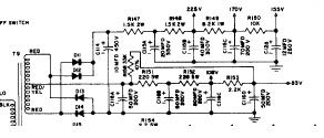
At 115B where I should have 225V, I have 250V. At 115C I have 190V instead of 175V. At C126, I have 170V instead of 155V. And that's with the Variac putting out 115-117VAC....:sigh:....:grumpy:
Suggestions as to how to fix this?
Took some quick voltage measurements. Here's the PS circuit...
At 115B where I should have 225V, I have 250V. At 115C I have 190V instead of 175V. At C126, I have 170V instead of 155V. And that's with the Variac putting out 115-117VAC....:sigh:....:grumpy:
Suggestions as to how to fix this?
dshoaf
That high voltage buzz
AA, that's probably about right. What I'd do is back off the variac until you get 225V at C115B. I'll bet that the line voltage will be somewhere around 110vAC. Once you've got 225vDC, then measure the other voltages downstream and they ought to be in line. Then check the plate voltages of the 6U8s and 12AX7s in the preamp and I'd expect them to be close to what's called for.
Cheers,
David
Cheers,
David
analog addict
Glory or Death!
Terry says....
...Not to worry about the higher voltages. The filaments run off a separate set of diodes, and should be fine. However, I will check the filament voltages to make sure I don't burn up my tubes....
BTW, Thanks Terry!....:yes:
...Not to worry about the higher voltages. The filaments run off a separate set of diodes, and should be fine. However, I will check the filament voltages to make sure I don't burn up my tubes....
BTW, Thanks Terry!....:yes:
analog addict
Glory or Death!
Running on the variac....
Had to put up one action picture....Sounds fabulous through a 45 SET amp and model 19's. Creamy sweet tooby goodness.... ...
...
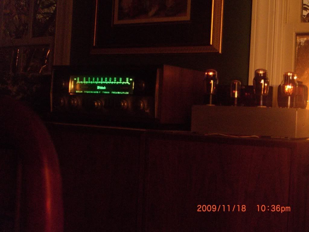
Had to put up one action picture....Sounds fabulous through a 45 SET amp and model 19's. Creamy sweet tooby goodness....
...
analog addict
Glory or Death!
well...
First, I reloaded the 12AX7 sockets with Tele smooth plates for the phono and a Tele ribbed plated for the combined preamp position. I need to find space for a TT in this system.
Anyway, a couple of impressions.
One: "FM" is louder than "MPX" I don't know why. Is the "FM" setting mono only?
Two: on "AUX" with a Denon CDP source on STOP, I can turn it up to the 1 O'Clock position on the volume knob and hear nothing with my ear pressed up against the 811 horn of the M19's.
Three: The detail and soundstage are amazing. Of course how much is amp and speakers it's impossible to say, but there is some real synergy here. I may have to switch in the 110Z I got from dshoaf just to see..
I will say one thing and that my other 110Z also seems to have some sort of issue with the FM. Sloober and I both heard it earlier this week when he came by to show off his new MC-30 rebuild (Beautiful job BTW. I'm envious)
Compared to a Yammie CT-1010 I had plugged into the AUX jack, the FM/MPX from the 110Z sounded dull, with no stereo separation. I get a stereo indicator light, but the sound's not right.
Anyone have any ideas????
dshoaf
That high voltage buzz
Anyway, a couple of impressions.
One: "FM" is louder than "MPX" I don't know why. Is the "FM" setting mono only?
Two: on "AUX" with a Denon CDP source on STOP, I can turn it up to the 1 O'Clock position on the volume knob and hear nothing with my ear pressed up against the 811 horn of the M19's.
......I will say one thing and that my other 110Z also seems to have some sort of issue with the FM. Sloober and I both heard it earlier this week when he came by to show off his new MC-30 rebuild (Beautiful job BTW. I'm envious)
Anyone have any ideas????
AA,
I'd suggest you let it run and settle in for a few weeks then recheck voltages on the circuits. I haven't had too much problem with resistors that changed values but it has happened. I think there's some reaction to older gear once they have gone through some heat-up/cool-down cycles. This was more pronounced with the MC-30s and MC-225s, where I ended up swapping out about 1/2 of the resistors. Still, it bears some monitoring; hence the recommendation.
Next, on the FM, I'm going to recommend a trip up to Knoxville to have Terry D align it. However, I would only do that once the voltages inside been confirmed after a month or so.
Sounds like that setup you have is singing well. Cool!
Cheers,
David
Similar threads
- Replies
- 0
- Views
- 1K