Restoring a Kenwood KR-9050

txturbo

AK Subscriber
Subscriber
24577727127_bb652c55fb_b.jpg

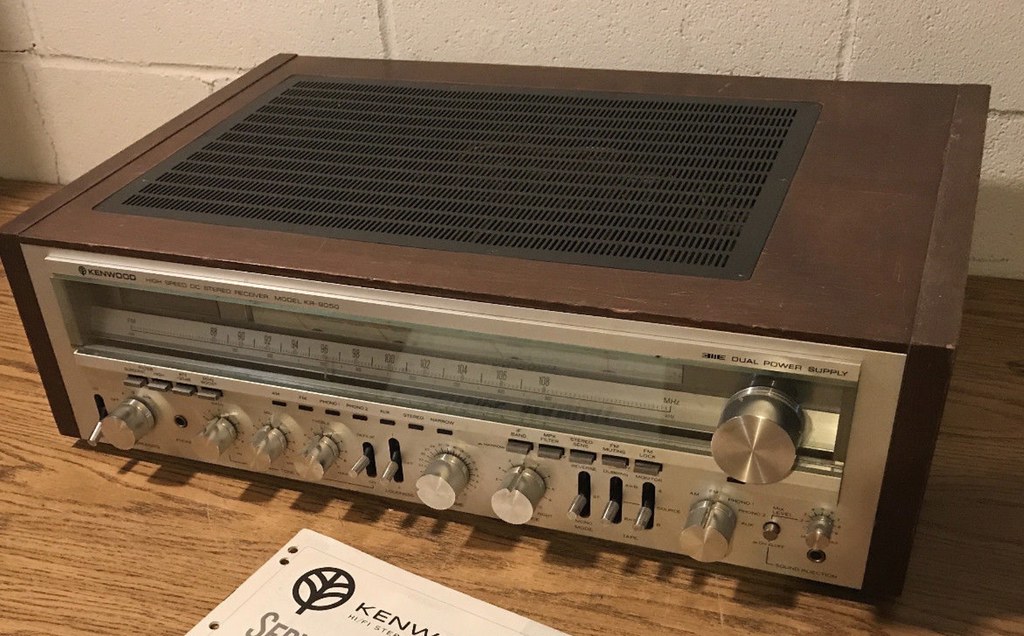
I picked up this unit in kind of rough shape. The seller said that he had some recent work done but soon after he got it back the left channel dropped out. It looked much better in the ad than in the flesh.

27666781979_52763cf4bc_b.jpg


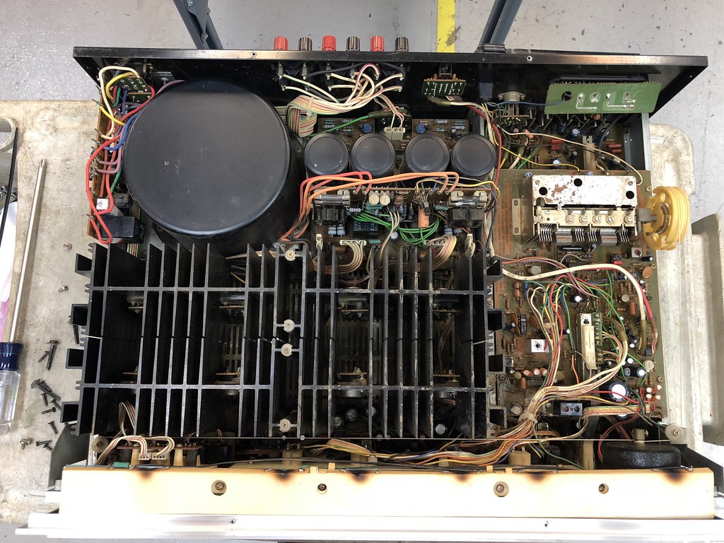
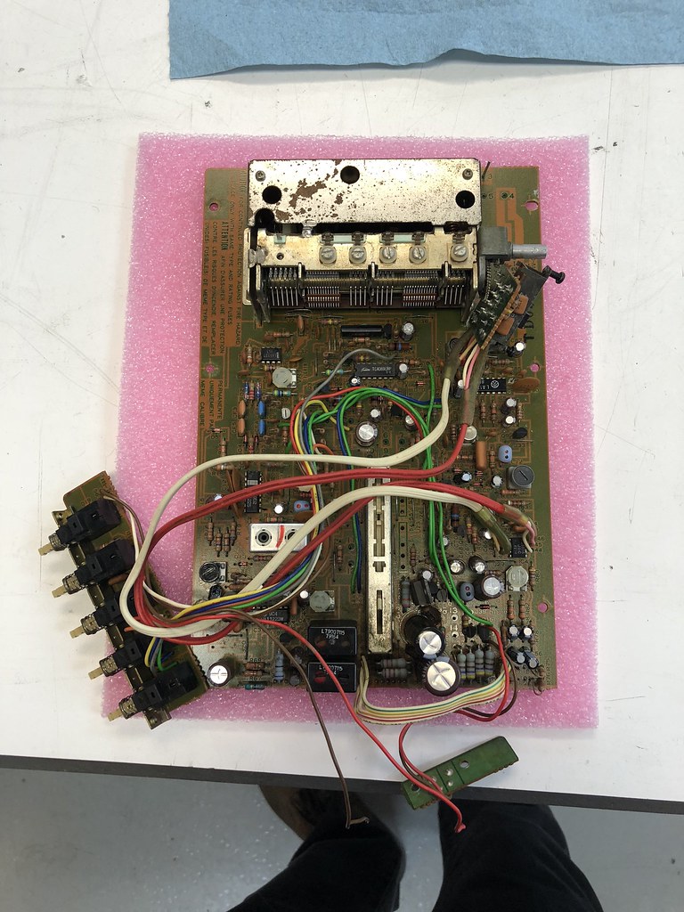
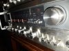
I gave it a quick evaluation, powers up, one channel plays, tuner wiggles when I turn the knob. The inside was filthy, maybe from a smoking environment, the wood case is in bad shape. The faceplate in blemish free with all of the lettering in tact and the knobs are in good shape. The lamps have burned holes in the cardboard. Previous work shows the outputs are a mix of NTE and other parts. This will require a full restoration.

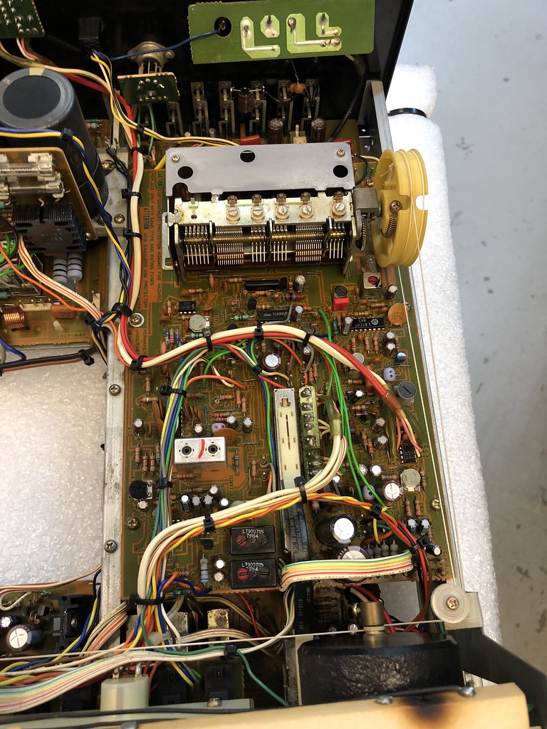
I started by stripping the faceplate and power amp section and bringing the chassis to the slop sink for a cleaning. The circuit boards have a layer of slimy gunk all over them that will not come off easily so I decided to use a technique that I previously used to clean a Marantz 2500 that had been in an attic for 20 years. Basically, what I did was to carefully soak the boards down with Windex avoiding the face of the receiver. The ammonia in the Windex breaks down the slime. With the boards nice and wet I use a paint brush to agitate and loosen up any hard to remove material. I then use water to thoroughly rinse everything off. I then use compressed air to blow as much water out as possible and wipe off anything I can. The next, and most important step, is to bake any water out. This is done using a small oscillating space heater for 8 hours. After about 20 min the receiver is quite warm to the touch and is basically dry. After 8 hours it is completely dry and baked out. The boards look much better but it’s still not really clean, I will clean them more thoroughly later.


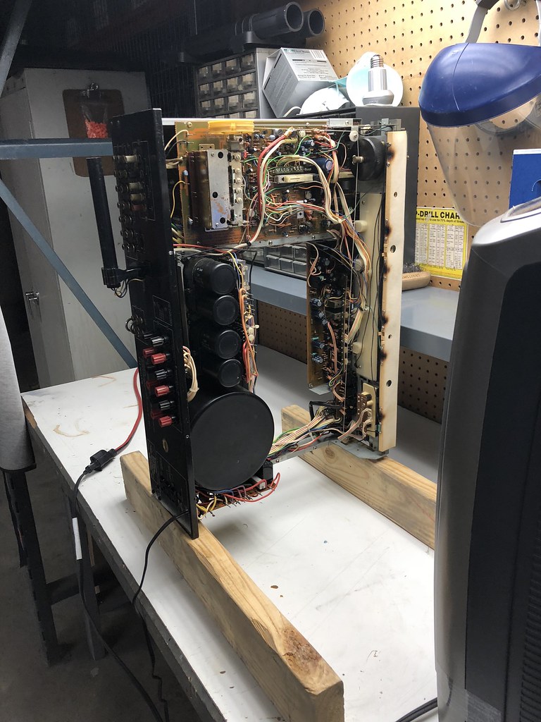
The next step is to remove the preamp and power supply sections for restoration on the bench. Even though it looks quite possible to do them without removal it's was way easier to work on the bench. I ended up pulling the tuner board as well.


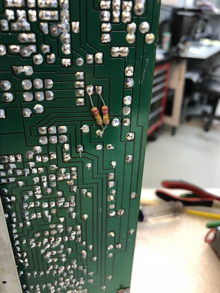
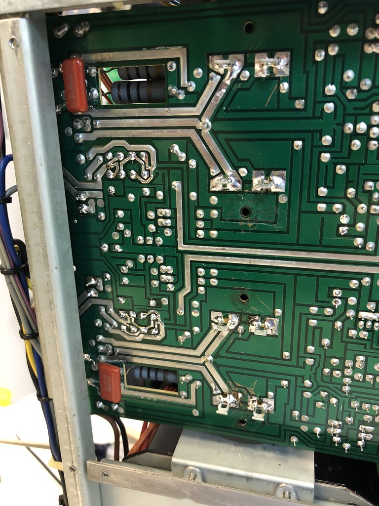
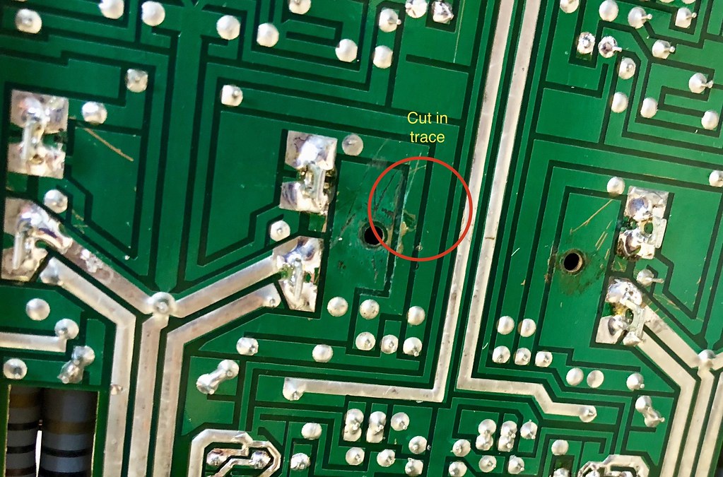
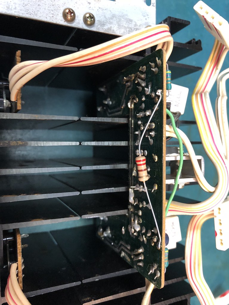
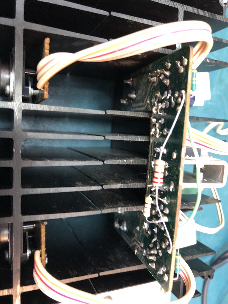
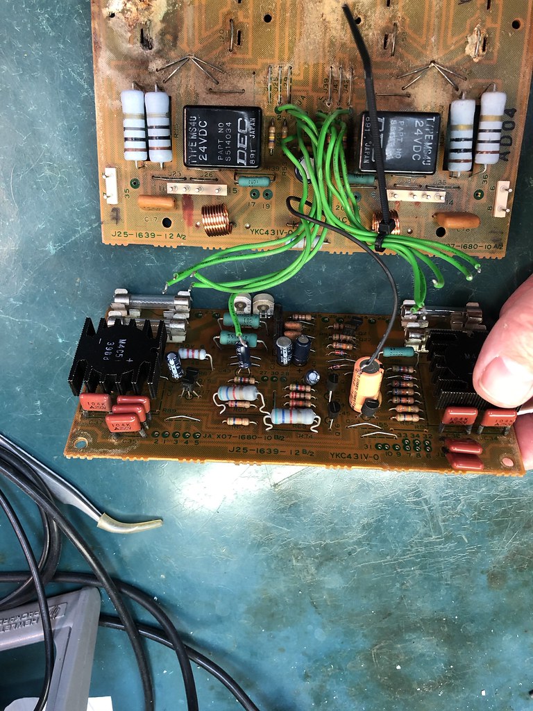
As I worked on the unit I could see signs of previous work by a hack technician. Mismatched silicon, tack soldered resistors and caps exct… I suspect that the technician was having problems with the amp oscillating and used some additional components in an attempt to solve the problem.

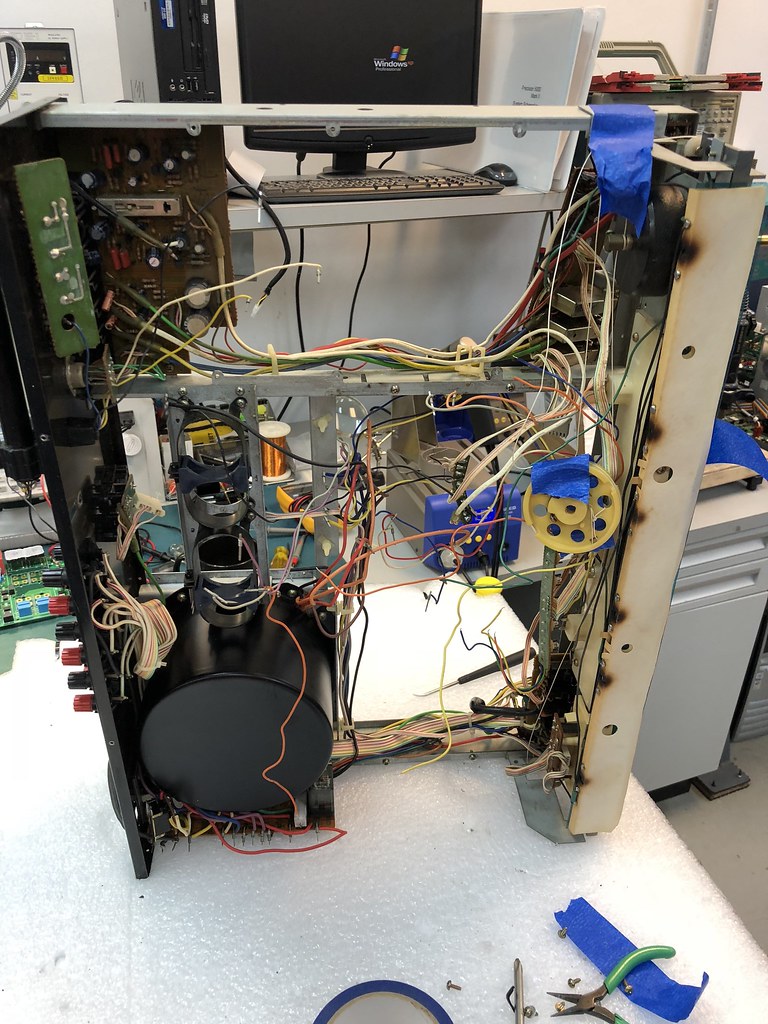
I also found evidence of rework in the incoming power section with the voltage selector bypassed because the switch had failed. I need to replace it.

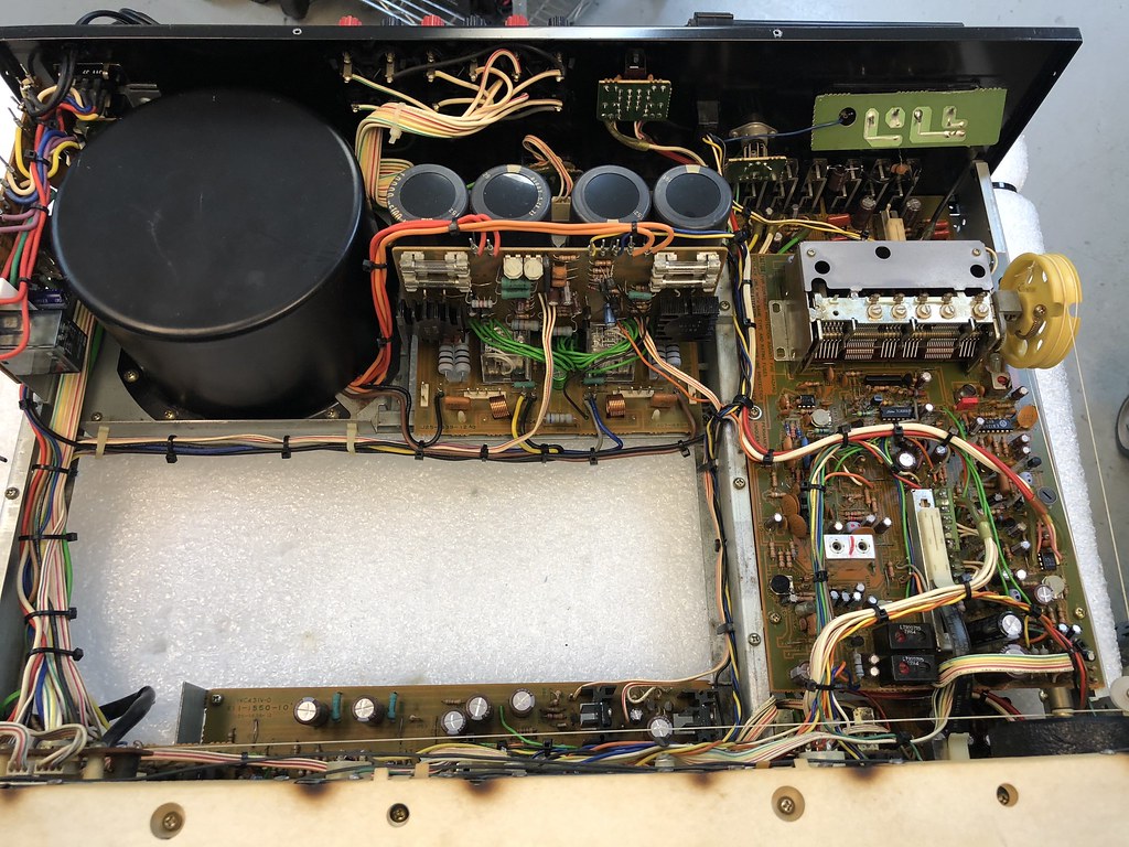
By the time I was done stripping the boards out and re capping the unit it was hardly recognizable.

27762530899_e8e7311db9_b.jpg


39172373625_5d7e275b53_b.jpg


The filter caps were leaking, bummer!

40071445161_163d83dc34_b.jpg


For this restoration I decided to keep the specs of the parts as close as possible to the original. This is a challenge since much of the silicon for the amp section was replaced with inferior parts. All of the original caps were ELNA's so I used ELNA SILMIC II's where possible. A few of the caps were specified as low leakage so appropriate Nichicon's were used. Sourcing the original ELNA filter caps was not possible so Nichicon KG 10000uF 100V Gold Tune electrolytic LKG2A103MKNF were used. Thees are drop in replacement at the same size and value. This was important since the solder tabs line up exactly. I had to order them from a place called Razzmatazz out of Italy, no one else had them. I could have gone with a sub of a different size and saved a few (actually a lot) of dollars but this would have gone against the theme of the restoration.

This brought me to the next issue... The amp section was a mess of mixed NTE crap. I was able to source enough of the 2SA1116 and 2SC2607 outputs. I had thought of using ON SEMI parts to do the job but they were not as fast as the 2SA1116 and 2SC2607's. At first I did not think this would be important however, after reading a bit about the KR-9050 I understood what the "HI-SPEED" marketing was about. Apparently the KR-9050's high speed meant that it had quite a slew rate, 100V/microsecond. Would it work with the ONSEMI parts? Not sure, but I suspect that it would. The FT of the 2SA1116 and 2SC2607 is 100 Mhz. Most modern ON Semi parts are 30 Mhz. Anyway, more $$$$ spent on parts. I am still waiting on the driver transistors, hopefully I will have them next week.

I will give the boards a final bath, removing all of the rest of the crap and flux. I do this by using a pan with denatured alcohol and a paint brush. I clean them, rinse and dry.

I dropped the cabinet off at my brother's house for new veneer.

I have a parts list that I will post when complete.
 
I spent quite a bit of time over the weekend working on the receiver. Finished re capping all of the boards and cleaning them.

In order to really clean the boards carefully most of them needed to be removed. I wanted to remove all of the old flux from the boards as well as any crud left on the surface. The boards were placed in a pan with de natured alcohol and then cleaned with a soft paint brush. The tuning cap was avoided. Once cleaned the board was rinsed and dried. The tuning cap shaft ground contacts were cleaned then the entire cap was rinsed with zero residue cleaner.

The tuner, removed.

39211136185_3591498512_b.jpg


After:

26270077528_2a08e74d38_b.jpg


I wanted to get the unit re assembled (before I forgot how!) so I spent Sunday and a bit of time Monday putting as much back together as I could.

39431930244_aab3ccaf21_b.jpg


Things left to do:

Sort out the tacked on caps and resistors.

This is the bottom of the tone amp board.
25271814767_205df96100_b.jpg


Caps on the power amp:

39244750015_ea18556c5c_b.jpg


There are also a couple of resistors tacked on to the small boards near the output transistors. I need to identify the locations in the schematic and see what they might be installed for?

I still need to build up the rest of the amp and deal with the lamps.
 
Outstanding work. Do the tacked on resistors look like something a tech did in the past to try to remedy a problem?

I'm looking at tacking on a resistor inside a turntable as a pull-down resistor for an IC that's not switching to the low state consistently. Any chance these were installed for similar reasons?

Maybe I should take a note to the next tech somewhere inside the table. :D

Cheers
Nathan
 
Time for an update....

The boards were finished and the receiver was assembled for testing.

39431930244_aab3ccaf21_b.jpg


I put the amp in and brought it up slowly on the varaic. The protect circuit was kicking in and out. A quick check showed that the rail +77 voltage to the drive transistors in the left amp was missing. I started checking from the rectifiers, it appeared that the left amp's was not working right. I pulled it out and checked it on the bench, all was ok. Tracing the power through showed that there was a break in a trace, looks like it came from previous work.

39504822194_f83a1b1bc4_b.jpg


With the trace repaired the DC on the speaker terminals was now adjustable to near 0 mV.

The next step was to adjust the bias. The manual has conflicting information. One part of the manual shows 20mv and another section shows 40mV.

26343722178_92dac18a7f_b.jpg


25345418807_564306d422_b.jpg


Maybe someone with experience on this can chime in? I was able to set the Bias to 20mV on the right channel but the left showed no bias.

In retesting the board while on the bench I found a resistor that that looked suspect.

The receiver now has adjustable bias on the left side. I set them to 20mV.

I listened for a while to the tuner and aux in with an ipad as a source. The tuner sounds really great. I will do a more through evaluation once I get everything finished.

Next I need to tackle the dial lamps. My plan is to use a piece of lexan to replace the paper section. The end of the lexan will have a 45 deg bevel, similar to the SX-1980. The lexan will have 5 holes drilled into the end with warm white LED's installed. Hopefully I can get that done this week. First I need to draw the part and take it to the plastic shop. While I am at it I will also replace the scratched plastic on the face.
 
Thees are the resistors that I was referring to:

25352552647_567b6545a0_b.jpg


25352552667_9ec407e6d5_b.jpg


I removed them.

There are the two resistors on the bottom of the tone amp board. Not sure if they are factory or not.

There are also two film caps on the bottom of the amp board. I suspect that they are not factory as well.
 
There are also two film caps on the bottom of the amp board. I suspect that they are not factory as well.

I was referring to the tone amp board photo, they look factory. The film caps and 220 ohm resistors you removed, do not.
 
I was referring to the tone amp board photo, they look factory. The film caps and 220 ohm resistors you removed, do not.

That makes sense.

Do you happen to have a picture of the underside of a 9050? Suprizingly google does not reveal any.

Any idea what the bias should be set at?
 
I don't have any photos. I've never worked on the 9050, as you've probably come to realize they are relatively scarce.

Concerning the bias. As you said the literature is conflicting, and with the 9050 being quite different from the 8050, which is 40mV biased, I'd think 20mV was the correct setting, but I don't know for sure.
 
After taking a careful look at the schematic I think that the bias should be 40mV. The schematic shows reference voltage measurements of 20mV + for Q5's emitter and -20mV for Q9's, making the difference between them 40mV.

40293299401_fc503044a5_b.jpg
 
I didn't realize there were four output devices per channel. The SM may be correct afterall. If you look at the SM measurement points for the 20mV bias setting they aren't the same as the connection points for the 40mV setting. My guess is they are both correct depending on where it is you take your measurements. If from the emitters of Q5 and Q9 then it would be 40mV, if from Q7 and Q11 then 20mV. Across Q5 and Q9 left channel (Q6 and Q10 right channel) would be the preferred measurement, so if you've done that you should be good to go.
 
Last edited:
I can give you a phone # of
A gentleman whom I am pretty sure can answer any thing.you need to know about your awesome Kenwood KR-9050. I myself am and have had a softspot for the monster KWs since they were new in the stores and I could only lust for such a magnificent piece of audio equipment. I did manage to scrape up funds for a KR-8010 which I had up until last year when an offer I could not turn down came along. I than found my dream Kenwood a KR-9600. It needed some love and all of us have heard the horror stories of impossible to find parts one of a kind and so on. Long story short Its as new or perhaps better. My cost was far below what seems to be a average medium. Call this number and ask for John
#206-728-0369. Be sure and have your questions in front of you and a pad for notes. I am sure he can help and can and will walk you through anything you are not quite sure of. If you have a bit of trouble getting through be patient. If some one ask to take a message be sure and include what info on what model as he is fond of the Kenwoods. I have him do my work and he is always on top of it. I do however only take my slightly unusual gear to him as some of the more common stuff he passes to a younger tech. I applaude
Your progress and look forward to hearing how the finished product turns out.
Good luck and let me know if you get what you need. John was responsable for many of the updates for kenwood after the products were in the hands of the consumer and was responsible for many fixes that kenwood utilized after the fact. Enjoy, Nemo. Washington state.
 
I didn't realize there were four output devices per channel. The SM may be correct afterall. If you look at the SM measurement points for the 20mV bias setting they aren't the same as the connection points for the 40mV setting. My guess is they are both correct depending on where it is you take your measurements. If from the emitters of Q5 and Q9 then it would be 40mV, if from Q7 and Q11 then 20mV. Across Q5 and Q9 left channel (Q6 and Q10 right channel) would be the preferred measurement, so if you've done that you should be good to go.

The schematic shows +/- 20mV for the all of the output emitters depending on position. You can't really see the "-" sign on the voltage reading for the emitter at Q11 in the BW picture above but in the actual manual the voltage readings are in red.

If Q7 and Q11 were both at +20mV the difference would be zero so one has to be negative. Since it has to be opposite in polarity the delta between them should be 40mV.

I did notice that the bias drifts a bit as the amp warms up.
 
You are far beyond my skill set I am by no means one whom would be of any real help. However at 10 am pacifc time call the number I gave you (if you didn't get it let me know) and you will be direct in touch with a gentleman whom worked closely with the designers of not only kenwood but all the manufacturers of the era. If memory serves me he started in 1964 and has worked 6 days a week since. He does this as much out of love of the days of glory. I have seen him bring life to equipment that was deemed unsaveable by all others. He has doner gear on hand that simply does not exist. I have a soft spot for the 9050 as it was the monster of monsters in the Kenwood line. Also my older brother had one. I am 12 years younger than he. As I said I purchased a KR-8010 as that was most I could afford. I did balance it out how ever as I managed to save enough to purchase a brand new pair of klipsch corner horns in walnut finish. They out did his set of 4 901s. I kept my old kenwood through the years but still had on the back burner of my mind the want of a top of the line Kenwood and did some bartering and finally 43 years later got my KR-9600
It is a beautiful thing but it did need a masters touch. I managed to meet with John and offered a barter for some other gear I had picked up in the last year. I am a professional truck driver. 11 months ago I had to come home as my eyesight was becoming a concern. I have had 1 surgery so far and habe at least 2 to go before I can even consider returning. My wife is the bread winner running the wheels off our truck while I am home bound. I started searching and buying vintage gear and got quite good at it. I am able to do minor work such as if a board if a board is toast I can source and repair or take something that has been mistreated clean and bring a non working piece back to a servicable item. I was able to keep my self occupied and was able to increase the level of equipment as timep progressed. I now have a large collection of unique and desirable equipment. I only have the one Kenwood the KR-9600
2 Sansui recievers a 881 and again a unit that I thought would forever be a impossible item a g-9700. The 9700 is the next piece that John will restore for me. I also have a carver 900, Pioneer 880 and a jvc5020. I myself am restoring a Harmon Kardon 730. I have mo speakers than any one person needs ×4. Klipsch, SDA polks,Walsh ohms,Speaker Lab super sevens my prize Klipsch are cf-2s I sold my legend 30s last year. I also have multiple turnables95 percent of my personal gear is circa late 60 thru 70s as I primarily listen to 2 channel stereo. I unfortunately am not the wizard. Frankly there are simply not that many true masters left. I do however know one of the last of an era. I gave uou his number. He will not charge you a dime and will ne happy to share knowledge with someone such as uour self. I am sure he has forgotten more than most will ever learn. I would tell you more but I can hardly even consider myself worthy to have the honor to know this man. If you need any info I suspect the very picture and the values are vivid in his mind. Please forgive me I am a music lover and he is the pied piper. I only ask when I drop a piece with him is it must out live me. In the seattle area finding equipment is not hard. Finding some one who can and will repair that gear is a different story. Lots of vintage seller and supposed service shops. I have seen how most work they charge for every thing they do or don't and in most instances the end result is the customer spent a.chunk of money to leave with their prized piece as sick or worse than it started. Call John tell him we talked on the forum. Tell him Jason from Marysville suggested you chat. I honestly think it will be to your good and you will have the correct info that will be clear and correct. I am close to my goals for my personal goals for equipment other than possibly a g-22000 or a g-33000. I love music but its ment in my mind to come from old school caps as big as a baked beans can. I have new stuff that is Home Theater new fangled disposible stuff. My feeling is if you can pick it up with out injuring your self I am more than likely not going to get excited over it. I apoligize for my ignorance but I believe my ability to recognize quality sound is as good or possibly above average. Its a therapy for me as if I am (god forbid) lose my sight prepared.
Hope for the best. But be prepaired for the worst.
The work you have done is beautiful! I believe you will be breaking it in sooner than later and hope you will send my way a image of the finished product. I apologize for the long drawn out story but I would prefer not to claim to be what I am not. I try to always to be of a service if I can. Cheers Jason B. If you check my profile there may be a picture or two of a I fraction of my gear. I just moved my daughter and her children out so I am im the process of setting up 2 dedicated listening rooms.
I love my 2 channel music.
 

Attachments

  • 20180203_023831.jpg
    20180203_023831.jpg
    93.7 KB · Views: 26
I have 2 KR 9050’s and 5 Kr 9600’s. 1 9050 and 1 9600 are nib. I listen to to 9050 all the time,it’s one of my favorites. I will see if I can see what it looks like underneath. I have a G22000. I like the 9050 better. The G22000 has been on a self for years.
 
I have 2 KR 9050’s and 5 Kr 9600’s. 1 9050 and 1 9600 are nib. I listen to to 9050 all the time,it’s one of my favorites. I will see if I can see what it looks like underneath.

Thanks!

I have the 9050 working good at the moment. I am waiting for my brother to finish the cabinet restoration. I will post pictures soon.
 
Back
Top Bottom