

Juan9568
Member
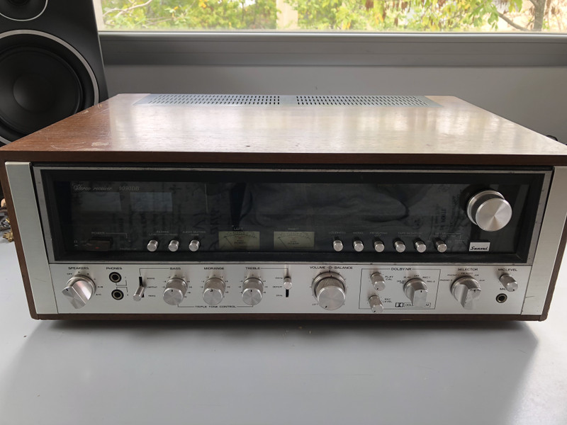
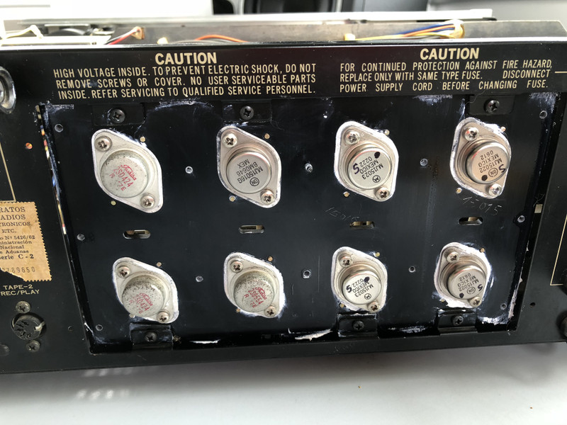
Hi guys. I'm about to begin with the restoration of my uncle's old Sansui 9090DB. The receiver is in a pretty bad condition, it has been serviced by bad technicians and they replaced parts with cheaper or wrong ones.
Issues:
. Burnt resistors
. Blown fuses
. Blown outputs
. Scratchy pots
A few months ago I decided to start with the restoration myself as there are no good technicians where I live and trying to get quality parts it's almost impossible.
I decided to do the following:
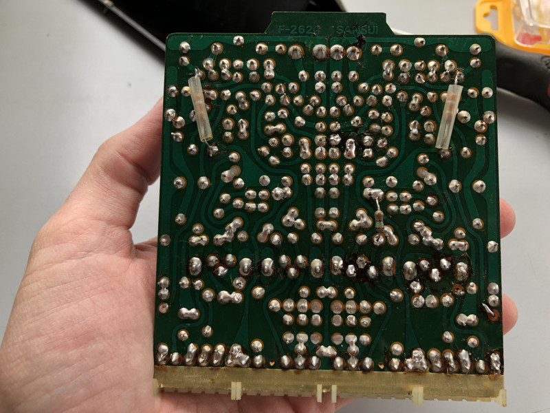
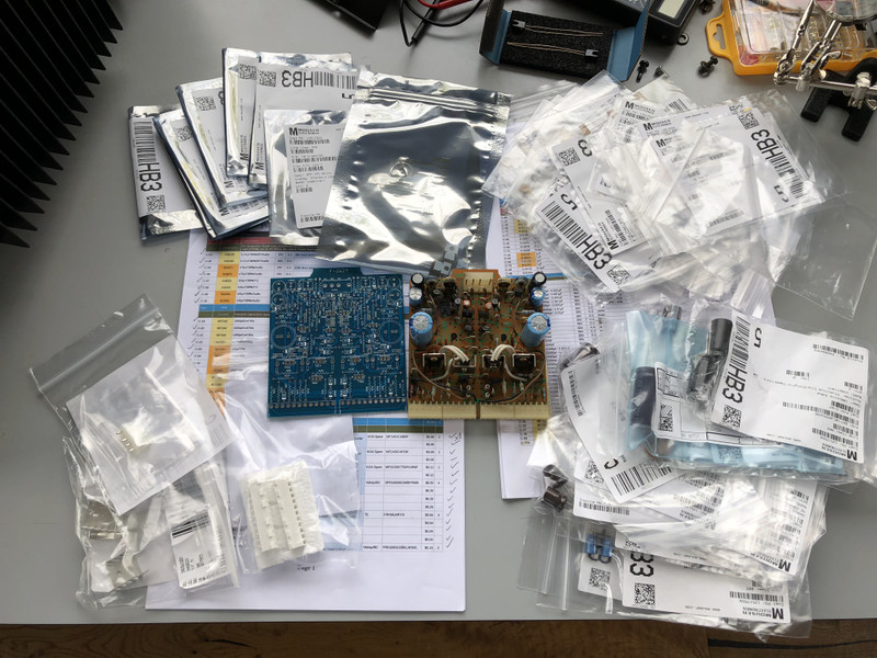
. Rebuild from scratch F2624 Driver board
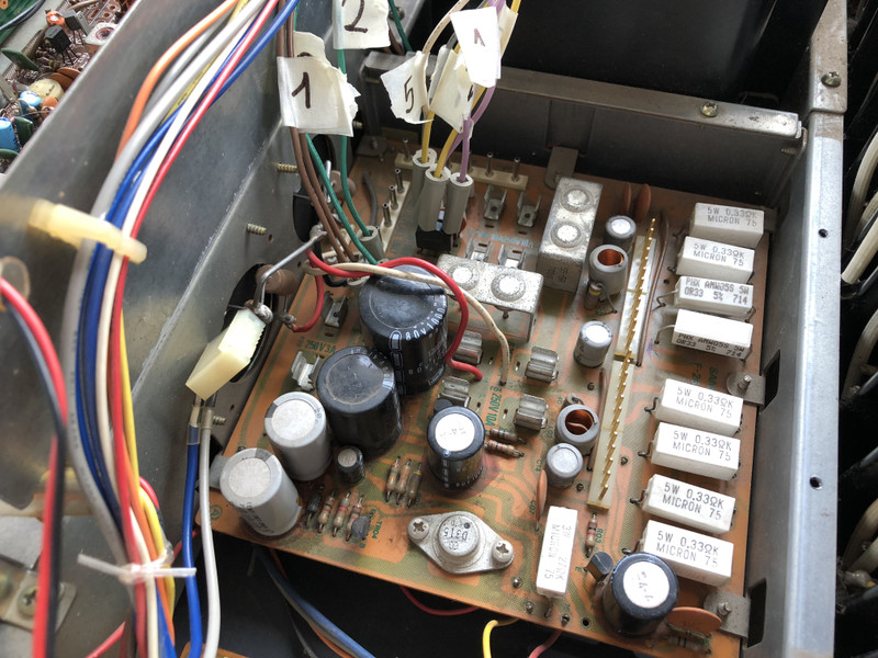
. Replace capacitors and resistors from F2656 Power supply
. New fuses
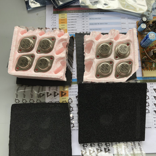
. New outputs
. Clean all pots
Because I'm not an expert in electronics I thought it would be easier for me to start with a new F2624 instead of troubleshooting the whole board. So I got the new F2624 PCB and most of the other parts from mouser and digikey.
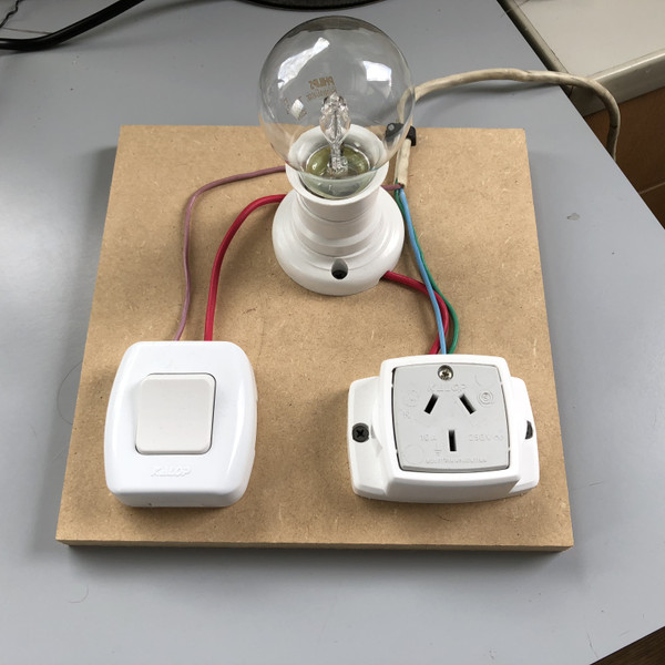
Also built myself a DBT cause I don't wanna blow everything up on the first run but I don't know yet what type of bulb I need to use for the thing to protect the amp, I got a 70W but don't know if it is the right wattage. I'm on a 220v area. Any suggestions??
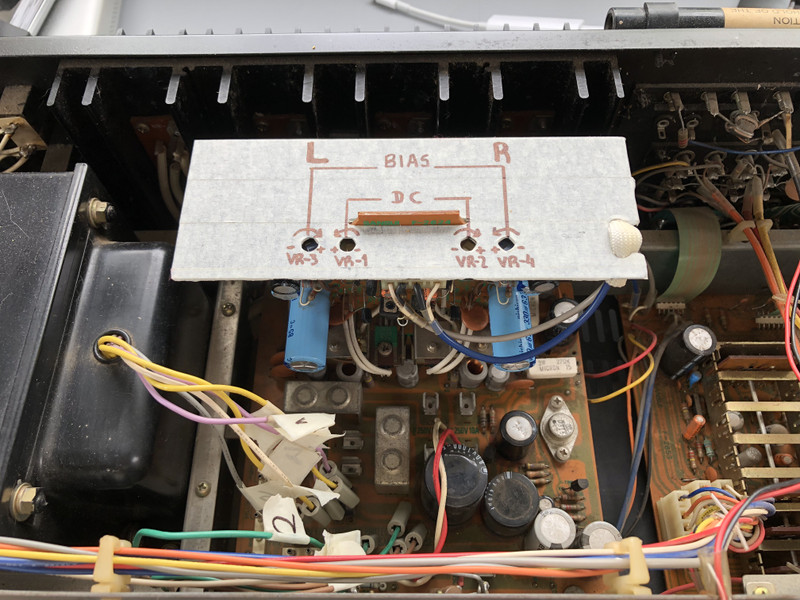
What most scares me is when time comes to adjust the DC and Bias current, I know it is a very fragile thing and needs to be done correctly.
I would really appreciate it if someone can give me any tips, tricks, suggestions so I can make this restoration right.
THanks!!!
Here are some pics of the amp before I begin. I will be posting updates on my progress.

Issues:
. Burnt resistors
. Blown fuses
. Blown outputs
. Scratchy pots
A few months ago I decided to start with the restoration myself as there are no good technicians where I live and trying to get quality parts it's almost impossible.
I decided to do the following:
. Rebuild from scratch F2624 Driver board
. Replace capacitors and resistors from F2656 Power supply
. New fuses
. New outputs
. Clean all pots
Because I'm not an expert in electronics I thought it would be easier for me to start with a new F2624 instead of troubleshooting the whole board. So I got the new F2624 PCB and most of the other parts from mouser and digikey.
Also built myself a DBT cause I don't wanna blow everything up on the first run but I don't know yet what type of bulb I need to use for the thing to protect the amp, I got a 70W but don't know if it is the right wattage. I'm on a 220v area. Any suggestions??
What most scares me is when time comes to adjust the DC and Bias current, I know it is a very fragile thing and needs to be done correctly.
I would really appreciate it if someone can give me any tips, tricks, suggestions so I can make this restoration right.
THanks!!!
Here are some pics of the amp before I begin. I will be posting updates on my progress.

