

mcgreg66
Member
Hi members,
After infected by the Sansui virus I came across a AU719 in good cosmetic condition but won`t come out of protection........
I checked a lot of things and took measurements but need some help of the professionals to interpretate and how to go on......
- when powering on protection led keeps flashing
- tried to set DC offset - left channel ok! (Incredibly sensitive to adjust!)
- right channel jumping DC; sometimes staying around 0mV then jumping over 40mV
- when trying to adjust DC relay starts trying to engage on and on but doesn`t stay
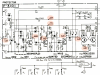
Checked voltages from the schematic
- PSU alright; all voltages little under schematic but i think ok! Probably different model series!
- drivers; both channels get 55v over pin 10 fine!
BUT now it starts
RIGHT CHANNEL / LEFT CHANNEL
TR16 - jumping 0-0,4v should be -0,55v. / Stable -0,57v!
TR15 - 0,9v falling to 0 going up to 0,9v aso. / Stable 0,63v!
TR14 - 0,03-0,05v should be 1,15v. / Stable 1,17v
R38 - 0- - 30mV should be 1,15v. / Stable 1,22v
So far I went....
The Protector comes after the drivers......
So I have for example 43-47v on pin 18 and 37-44v on the relay coil.
For sure it stays in protection!
Any suggestions!
Many Thanks
Gregor
After infected by the Sansui virus I came across a AU719 in good cosmetic condition but won`t come out of protection........
I checked a lot of things and took measurements but need some help of the professionals to interpretate and how to go on......
- when powering on protection led keeps flashing
- tried to set DC offset - left channel ok! (Incredibly sensitive to adjust!)
- right channel jumping DC; sometimes staying around 0mV then jumping over 40mV
- when trying to adjust DC relay starts trying to engage on and on but doesn`t stay
Checked voltages from the schematic
- PSU alright; all voltages little under schematic but i think ok! Probably different model series!
- drivers; both channels get 55v over pin 10 fine!
BUT now it starts
RIGHT CHANNEL / LEFT CHANNEL
TR16 - jumping 0-0,4v should be -0,55v. / Stable -0,57v!
TR15 - 0,9v falling to 0 going up to 0,9v aso. / Stable 0,63v!
TR14 - 0,03-0,05v should be 1,15v. / Stable 1,17v
R38 - 0- - 30mV should be 1,15v. / Stable 1,22v
So far I went....
The Protector comes after the drivers......
So I have for example 43-47v on pin 18 and 37-44v on the relay coil.
For sure it stays in protection!
Any suggestions!
Many Thanks
Gregor
Attachments

Last edited:
