
Rob DeFries
Active Member
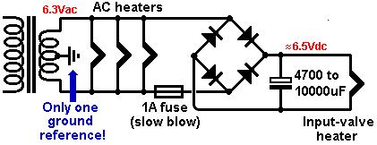
I made the mod separating the heater from main board ground. The heater voltage measured the same before and after the mod.
AC line: 124 VAC
Heater: 6.77 VDC
Ripple: .61 VAC

I made the mod separating the heater from main board ground. The heater voltage measured the same before and after the mod.
AC line: 124 VAC
Heater: 6.77 VDC
Ripple: .61 VAC
I am planning to replace the coupling caps in this schematic, the stock "audiophiler" caps are 1uF 400V. I am planning to upgrade to 2.2uF, but options in 400V are few and far in between. most of the good stuff is in 250V. I see a few folks have replaced them with 250V caps, but from a circuit design point of view, I like to use caps which run at half their rated voltage, and I am not sure how the voltage levels run in a tube - In a transistor, I can figure out the bias voltages & calulate the voltage the cap sees, and figure out how much I need, but with tube circuits, I am lostI believe this is preamp stage schematic:
")
Thanks natger, good to know. I was considering picking up some GE 5670's, do you know how the 6n3p-ev compares?BTW overall hiss level with 6n3 is higher than with 6n3p-ev, this while treble and bass and everything else is lacking with 6n3 in comparison.
American or Russian might be better ? But difference with chinese is a difference you normally won't find between cheapest cdplayer and a high end cdplayer, or cheap amp and a Krell or Audio Note amp. The difference is huge for audio. It is more like comparing a nobrand $5 speaker with some Kef or AndrewJones Pioneer if your in US. Something like that. It is a constant voltage sink, the ones I used are ~1.6V red, very low intensity, low ~constant resistance of about 6 ohms, 0805 smd

