

You are using an out of date browser. It may not display this or other websites correctly.
You should upgrade or use an alternative browser.
You should upgrade or use an alternative browser.
SP1200, 1700, or 2500 Crossover Diagrams
- Thread starter Culpeper
- Start date


OK. Got the microphone in yesterday and installed REW. I've been playing with it this morning, getting the room dimensions right, etc. Here is the graph of the speakers together, 1/6 octave smoothing on each setting, clear, neutral and soft. All this is a bit new to me, so it may take some trial and error getting each driver in the box as a ZMA file. Most of that will be setting up the mic to get rid of as much of the room as possible. This is the pair with coil and zobel installed, old capacitors in the crossover. There's a significant dip around 600, and makes me think that maybe a 1.2 coil instead of the 1.5 would work a bit better by pushing the coil crossover point upwards to 800ish. Of course, the old caps could be causing issues being way out of spec.
Attachments

Last edited:
.frd files finished. I measured them as mounted in the box, so there's 5 total. L/R mid, top/bottom Tweeter and woofer. Measured 1 meter away, nothing within 5 feet of speaker, 9ft ceiling and about 2.5 ft off the ground. 1/12 octave smoothing.
Going to email those to you.
Going to email those to you.
Attachments

Something I didn't think about until I measured each speaker, and that was setting my tone flat on the receiver. I was thrown off by was Xsim had versus what REW heard.
I re-did the response of the Munford Ecap and zobel circuit with the flattened tone, and was fairly surprised at the similarity between Xsim and the actual measurement. I will note, the tweeters and mid are parallel, woofer in series in Xsim. Xsim didn't see that huge dip around 700 though, which has me scratching my head......box maybe?
I re-did the response of the Munford Ecap and zobel circuit with the flattened tone, and was fairly surprised at the similarity between Xsim and the actual measurement. I will note, the tweeters and mid are parallel, woofer in series in Xsim. Xsim didn't see that huge dip around 700 though, which has me scratching my head......box maybe?
Attachments
Last edited:


I've tinkered around some, and while you really can't "flatten" these speakers out, I managed to clean up what I could. Wish I could explain the hole at 150 outside of just being the speaker itself. Dip at 1k won't go away unless you delete the coil from the woofer entirely.
I checked my old and new crossovers, all are 16k.
I checked my old and new crossovers, all are 16k.
Attachments

Culpeper
Active Member
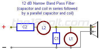
I'm wondering if just changing C2 to to suit the system would bring that crossover where it is supposed to be for the SP2500 at about 890/6800 on the Natural setting. I'm getting 15uF for C2 in the diagram above and the inductors are as measured as posted on page 1. All other capacitors stay the same.
I've tinkered with those numbers, and couldn't do anything to get that low side of the mid to get a lower crossover point. Seems only to change in db. I'll show you where I'm at on this, may go a cheapy route and slap this together to experiment with. Coil values kinda have to change some. I shot for a point between clear and natural. I also upped the resistor value on the mids, which brought it more in line with the tweeters.
Attachments


Similar threads
- Replies
- 28
- Views
- 8K
- Replies
- 0
- Views
- 2K