

You are using an out of date browser. It may not display this or other websites correctly.
You should upgrade or use an alternative browser.
You should upgrade or use an alternative browser.
Suggestions/advice for M-80 service....
- Thread starter analog addict
- Start date
analog addict
Glory or Death!
Where would you suggest I get the heat sink thermal compound? Digikey? Mouser? Somewhere else? I'm always looking for the best deal, since I'm a cheapskate....
Maybe amazon..I usually get it from Mouser (Wakefield-Vette)
http://www.mouser.com/ProductDetail...=sGAEpiMZZMvJqaFk9BIiv9zsHXowjRHoMnWoS8fNaP8=
http://www.mouser.com/ProductDetail...=sGAEpiMZZMvJqaFk9BIiv9zsHXowjRHoMnWoS8fNaP8=
analog addict
Glory or Death!
Progress.....
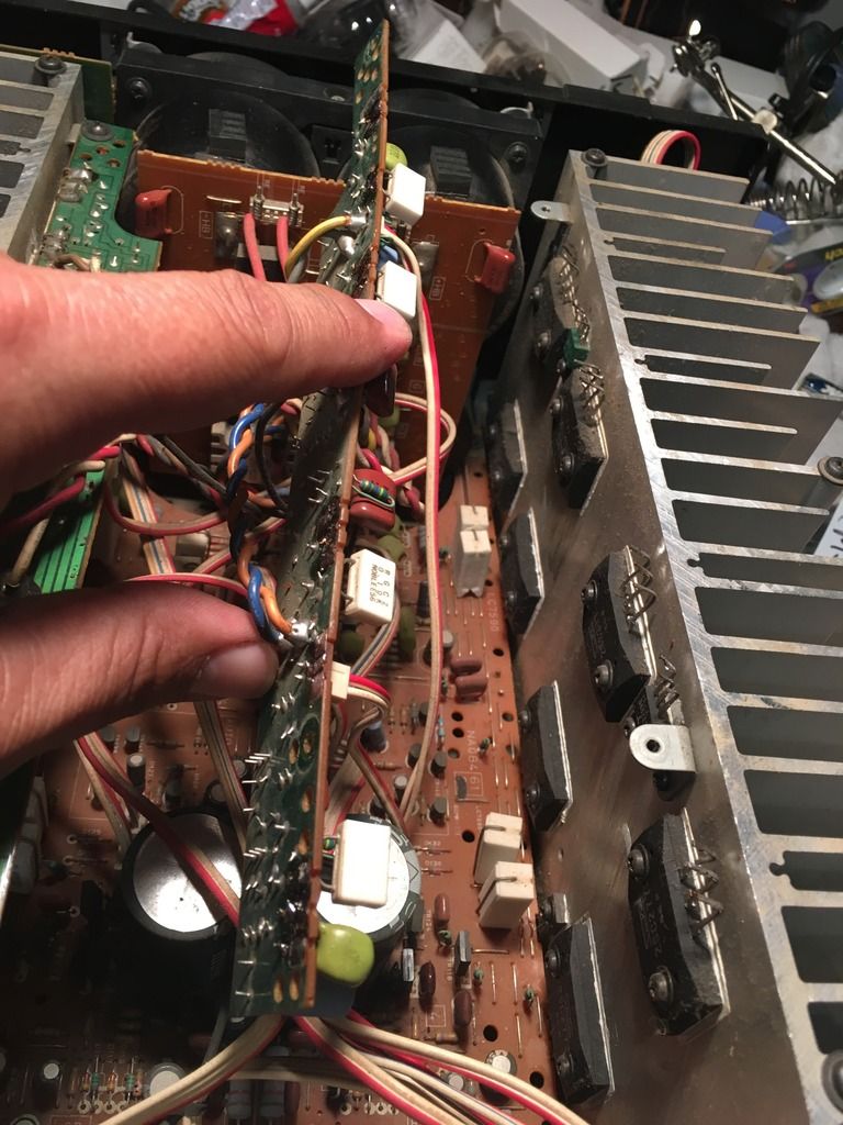
Unsoldering the small top boards....
One side unsoldered, and the two screws removed. The plug in connectors have been marked, and removed as well.
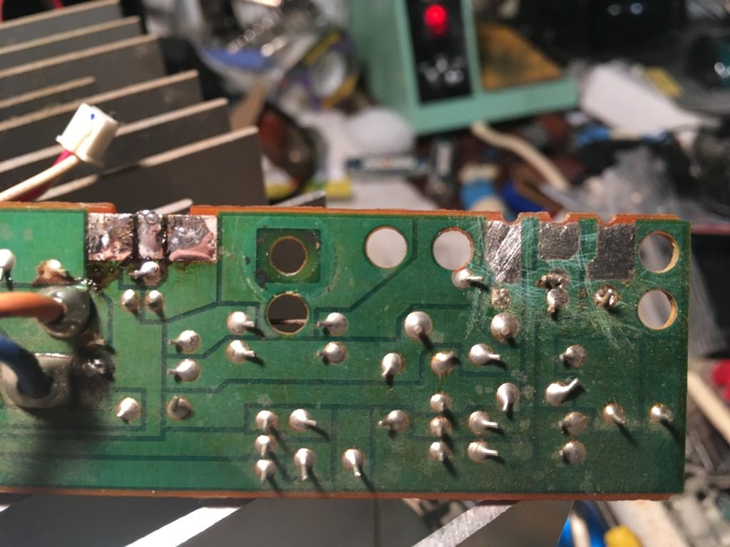
Cleaning up the pads for connecting on reassembly...
The underside of the main PCB board, with the left side unsoldered...
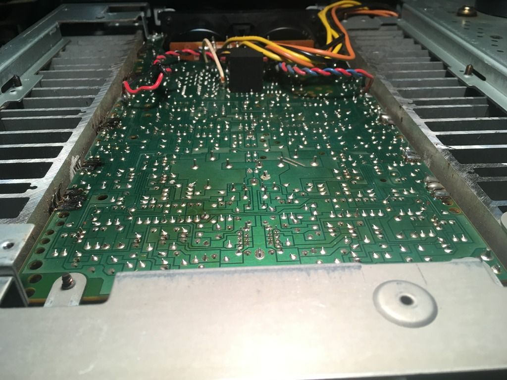
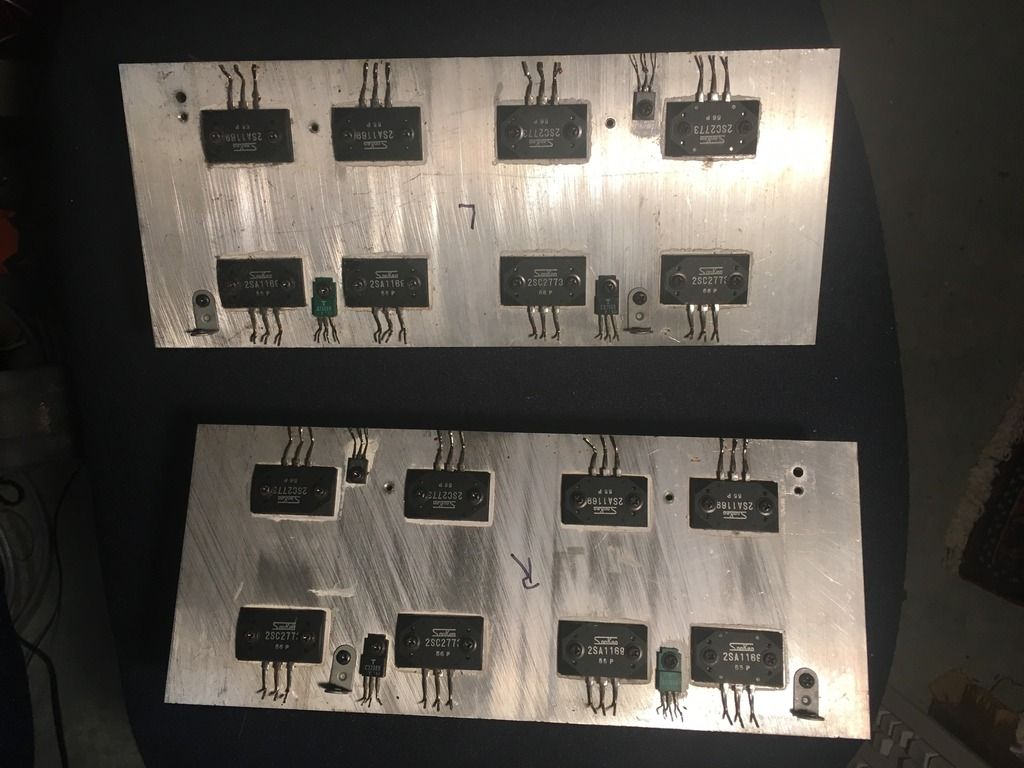
All connections unsoldered, and the three long screws per side removed, allowing simple lifting out of the heat inks and associated transistors.
What remains.....
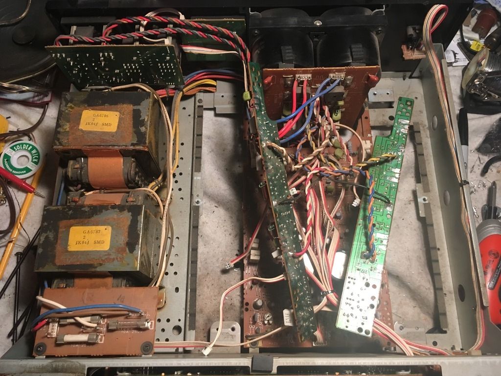
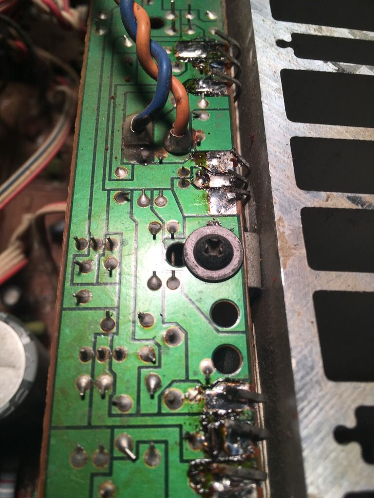
Including this mess.....
Guess I'll need to find and carefully read that thread on glue removal. Can I unsolder the big caps and remove them first?
Unsoldering the small top boards....

One side unsoldered, and the two screws removed. The plug in connectors have been marked, and removed as well.

Cleaning up the pads for connecting on reassembly...

The underside of the main PCB board, with the left side unsoldered...

All connections unsoldered, and the three long screws per side removed, allowing simple lifting out of the heat inks and associated transistors.

What remains.....

Including this mess.....


Guess I'll need to find and carefully read that thread on glue removal. Can I unsolder the big caps and remove them first?
Last edited:
Absolutely..Can I unsolder the big caps and remove them first?
analog addict
Glory or Death!
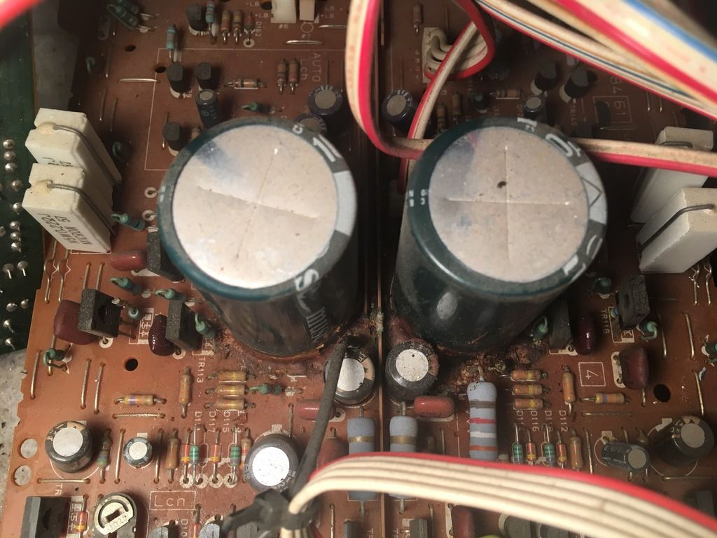
Back to this project. Took the two 220uF/6.3V caps off as well. Nice caps, Black Gates. Too bad one of them is open circuit with the lead loose internally, prolly when I wiggled it loose with the soldering iron. The 1000uF/100V caps both measured OK with a capacitance meter and ESR meter. Anyway, Here are some pics of the progress...
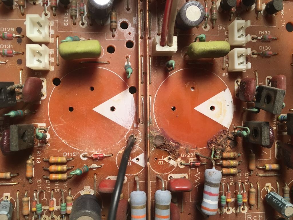
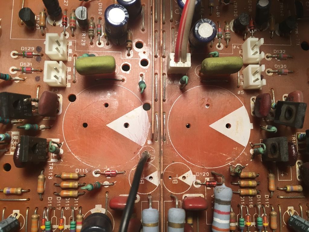
Would like to measure some of these other components before replacing the caps. Can anyone tell me what the upright resistor is at the 5 O'clock position by the right sided large cap?


Would like to measure some of these other components before replacing the caps. Can anyone tell me what the upright resistor is at the 5 O'clock position by the right sided large cap?
Can anyone tell me what the upright resistor is at the 5 O'clock position by the right sided large cap?
R126 -- 330Ω 5% 1/4 watt flameproof . Schematic is incorrect. Schematic says 390Ω. Actually installed is a 330Ω ( orange/orange/brown/gold)
analog addict
Glory or Death!
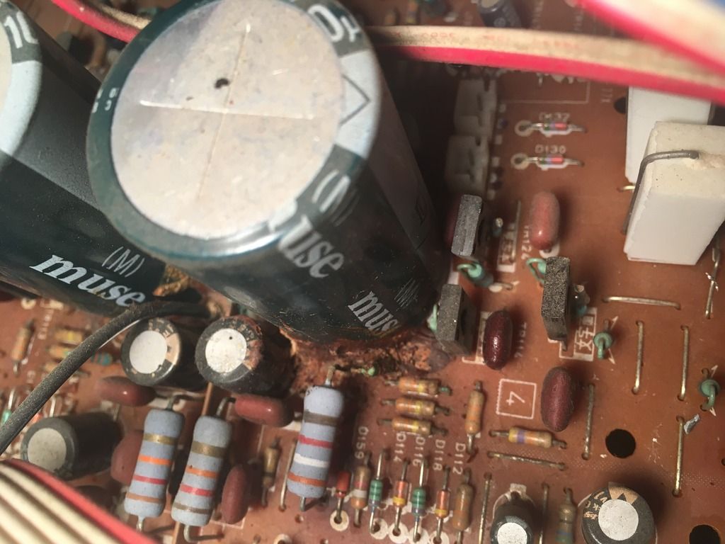
Thank you sir. Been using an acetone based nail polish remover. Luckily doesn't leave any noticeable residue. The two Zener diodes D119, D120 in the affected area measure identically, 722(ohms) in one direction, 1253 in the other. The only other potentially affected resistors are a couple of 470 ohm ones, and they both measure in spec as well. I'm going to put the caps back in and start working on the power transistors.....
3 volt 500mw zener. (RD3.0EB2) I use these they are exact replacements.The two Zener diodes D119, D120
http://www.mouser.com/ProductDetail/Nexperia/NZX3V0C133/?qs=/ha2pyFadugKwfmvw1lENeCyvwPIVspidVjBNowgKK3/GrD03LKpyA==
analog addict
Glory or Death!
Putting together a parts list parts. Also finally noticed the HD service manual on the M80/M85 tips thread. 
So far I have the 1000uF/100V caps, the 220uF/6.3V (10V) caps, the 330/470 ohm 1/4 W resistors, Zener diodes, 1Kohm/0.5W single turn pots, all 3 relays and thermal compound. Should I just get C164 - 47uF/25V cap as well?
However I can't find R231/232 on the parts sheet. Ideas?
For the 1/4 W resistors, I was planning on ordering these, assuming they're the right type...
http://www.mouser.com/Search/Produc...rtualkey66000000virtualkey660-MF1/4LCT52R471J
Also, before I order parts is there anything else I can do to assess the Meter board? Other than the intact fuse and the sticky switch, I haven't got any idea what to do next. Maybe I have to get the rest of the amp up and running, and that's fine, but I was hoping not to have to place two separate orders if possible.....TIA
On the parts sheet . First page. Bullet statement at the top of the list. -- Resistors not listed in the parts list are 1/4 watt carbon film.--However I can't find R231/232 on the parts sheet. Ideas?
R231/232 are 330kΩ 5% 1/4 watt - either carbon or metal film.( orange/orange/yellow/gold) There are 3 each of these in parallel per channel. Usually 1 each per channel is corroded from the glue.
For the 1/4 watt resistors I use various makes that specify in the spec sheets as "flame resist or flameproof coating". About the only thing on the meter board that I address is the electrolytic caps and lamps if required.And of course sticky switch issues.
Last edited:
analog addict
Glory or Death!
Thanks Dave. I'll pull any stray parts together from other current projects and order it up....
analog addict
Glory or Death!
Got the parts, and back to working on this. Did all the components on the main board. Caps are all - terminal on the white triangle marking. Can anyone confirm that I got the Zeners polarity right?
https://www.flickr.com/photos/152201018@N03/shares/0o529n
Now that Photobucket has truly gone off the deep end, I'm transitioning to Flickr, but I haven't quite got the hang of it yet....

https://www.flickr.com/photos/152201018@N03/shares/0o529n
Now that Photobucket has truly gone off the deep end, I'm transitioning to Flickr, but I haven't quite got the hang of it yet....
analog addict
Glory or Death!
Thanks Dave. I have all three relays to do and then I'll replace the thermal paste and reinstall the outputs and heat sinks, if not today, in the next couple. Any tricks to getting the relay board taken down?
Need to remove the rear panel enough to allow the relay board to be removed from the rear panel. Unsolder speaker A & B binding posts then you should have enough room to remove and replace the relays.Kind of a PITA.Any tricks to getting the relay board taken down?
analog addict
Glory or Death!
photo bucket zapped your photos
Yeah the bastards want mucho dinero to be able to share pix now. F them.
I'm done with Fotofukit. Now someone has to tell me how to embed pix from Flickr.
Anyway, back to the restore.
here's the dismounted relay board, and the replaced relays. Love my solder sucker.
https://www.flickr.com/photos/152201018@N03/shares/DV03w8
I decided to paint the top of the transformers after taking off the rotting foam.
https://www.flickr.com/photos/152201018@N03/shares/w9fo3c
Any hints on how to properly dismount and remount the output transistors with new thermal compound?