Suggestions/advice for M-80 service....

As far as I'm aware Dave Wojo still sells bulbs, he should be able to sort you out:
https://sites.google.com/site/dgwojocom/

Being outside the US, I'd love some details on those bulbs still, if anyone could share links to plausible replacements online.

Is there any recommended way to convert those three to LEDs?
 
Yes. Dave offers LED replacements for these bulbs. I should have mine by Sat. Email him. He will probably be able to ship international....
 
Last edited:
Lamps came in. Time to fish or cut bait.

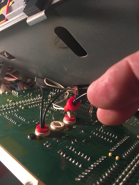
Putting new bulbs in. Using Warm LEDs from Dave Wojo

Untitled by Analog Addict, on Flickr

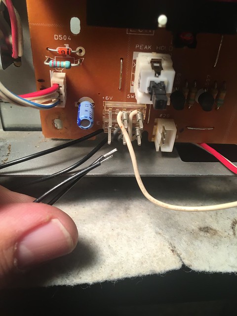
Didn't realize that these were wire wrapped. Ugh...

Untitled by Analog Addict, on Flickr

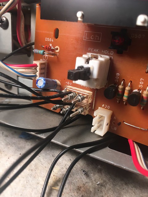
All wrapped up

Untitled by Analog Addict, on Flickr

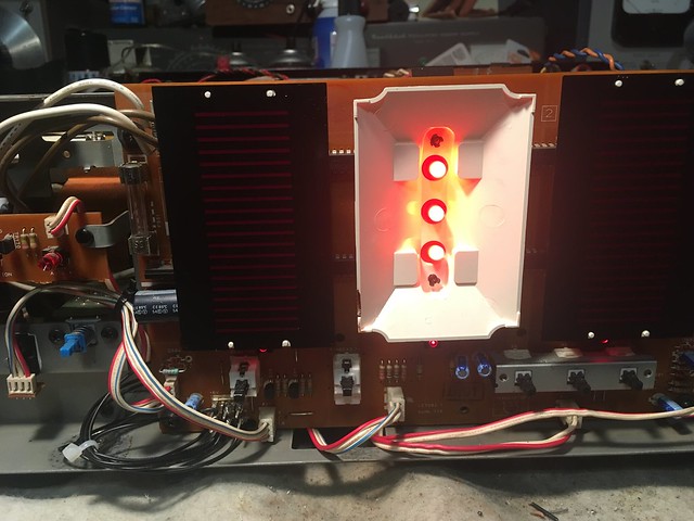
Sweet!

Untitled by Analog Addict, on Flickr

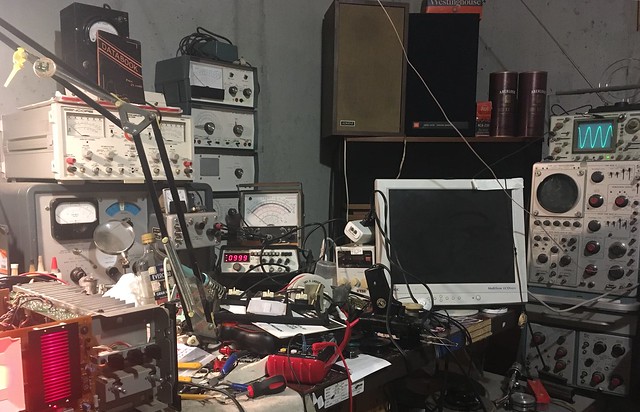
Doing the meter calibration. Glad the old scope still works...

Untitled by Analog Addict, on Flickr

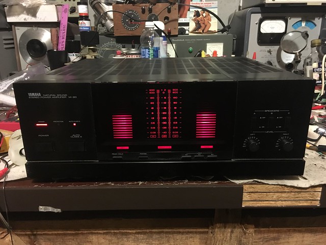
All systems go! Looks like we have a winnah!

Untitled by Analog Addict, on Flickr
 
Took this amp over to Dennis Had's shop to have him test it on the bench. Looks like it's making an honest 250 WPC...

Untitled by Analog Addict, on Flickr

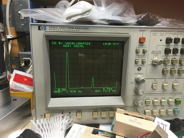
As expected, primary distortion is 3rd order, but 50 db down from the primary 1KHz signal. Nice and clean

Untitled by Analog Addict, on Flickr

We started having problems with the unit going into protection on the bench, and after a bunch of profanity, Dennis realized that the positive and negative alligator clip leads from the OEM speaker terminals to his test equipment had melted together due to the abnormally large number of electrons flowing through them. So basically we were running the unit into a dead short on one side. I'm happy to say that the protection circuit works perfectly as well, and that amp is unharmed.

Untitled by Analog Addict, on Flickr
 
I have the M80 also . I cleaned the glue and changed all the electrolytic caps except the main power caps . Got lucky with the glue and only had to change two diodes . The amp works and sounds good but i think it is not working at its full power potential . side by side with my Yamaha M65 , the M80 does not seem to put out near the same amount of power that the M65 does. The M80 seems to be lacking in the bass department as well. Basically the M65 smokes the M80 . My question is ! Does the M80 need new main power caps or is this a relay problem? Any suggestions would be welcomed.
 
I have the M80 also . I cleaned the glue and changed all the electrolytic caps except the main power caps . Got lucky with the glue and only had to change two diodes . The amp works and sounds good but i think it is not working at its full power potential . side by side with my Yamaha M65 , the M80 does not seem to put out near the same amount of power that the M65 does. The M80 seems to be lacking in the bass department as well. Basically the M65 smokes the M80 . My question is ! Does the M80 need new main power caps or is this a relay problem? Any suggestions would be welcomed.
What exactly did you replace C164 with?
 
I have the M80 also . I cleaned the glue and changed all the electrolytic caps except the main power caps . Got lucky with the glue and only had to change two diodes . The amp works and sounds good but i think it is not working at its full power potential . side by side with my Yamaha M65 , the M80 does not seem to put out near the same amount of power that the M65 does. The M80 seems to be lacking in the bass department as well. Basically the M65 smokes the M80 . My question is ! Does the M80 need new main power caps or is this a relay problem? Any suggestions would be welcomed.
Check the solder connections of the TO-220 transistors on the narrow APS boards.( power supply circuit board 3)
They are full plastic case TO-220's
 
Last edited:
They are full plastic case TO-220's
These transistors control the 8 upper MT-200 sanken rail switching transistors. ie.+/-HB & +/-LB
The 8 bottom MT-200 sankens are the output transistors.
Those TO-220 transistors hanging upside down tend to develop annular ring cracks in the solder connections. Which prevents the +/- HB(high power) from switching in when needed. Thus limiting the rail voltage to just +/- LB(low power) which prevents the amplifier from achieving high output power.
 
Last edited:
I changed all the caps with the same values as original . Some voltages might be slightly higher but the same UF . Not sure about C164 . If your referring to the single Bi Polar cap , I remember its UF is the same but the voltage rating was kind high on that one. I did re solder a lot of places on the main board. I will check the APS boards . Is this unit better biased at 10 or 15 mv ? Also the amp gets pretty hot in about 5 minutes of playing . Does sound like half power . Thank you for the info . I will check all those areas .
 
The M-80 is electronically the same as a M-85. the only difference is whats printed on the front and rear panel. Both make the same amount of power in Class AB and class A roughly
295wpc @ 8Ω @ 1 khz. I use the M-85 service manual for both the M-80 and M-85.
 
Also the amp gets pretty hot in about 5 minutes of playing
Amplifier may be oscillating.. It will get hot in class A ..but should not in classAB ( normal ). In class AB the power transformers should be warmer than the heatsinks.
 
Well I reflowed pretty much all the joints on the APS boards and still have the same low power and heat problem . Not using the class A button . The bi polar cap is 47uf 100v. Had previously reflowed many many joints on the main board when I recapped the unit . This unit had the broken speaker Jack's and was in protection mode when i bought it (100 dollars ) . Fixed the Jack's cleaned the glue , replaced two zeners and she came out of protection mode and now we are here .
 
It was around the two large caps on the main board . The two diodes in front of those caps where trash. Two flame proof resistors where questionable but tested good .
 
It was around the two large caps on the main board . The two diodes in front of those caps where trash. Two flame proof resistors where questionable but tested good .
How about the two jumpers right next to the copper buss bars?
 
What about the big cement block resistors.
Those are either emitter resistors for the output transistors or ballast resistors for the three protect relays. Emitter resistors .22 Ω / 5 watt.. Ballast resistors are 390Ω / 5 watters. The emitters resistors very seldom drift. Usually if they go bad it is from a shorted output transistor and they burn " open ".
 
Back
Top Bottom