

You are using an out of date browser. It may not display this or other websites correctly.
You should upgrade or use an alternative browser.
You should upgrade or use an alternative browser.
SX-535 Re-Capped, but Buzzing Returned
- Thread starter Natalya
- Start date
UncleBingo
Super Member
Those look okay. They could still be bad, but they aren't showing obvious visual signs.
First, let me say WELCOME to ") Audiokarma, and a BIG Welcome to a fixer in training!!!
Audiokarma, and a BIG Welcome to a fixer in training!!! .
.
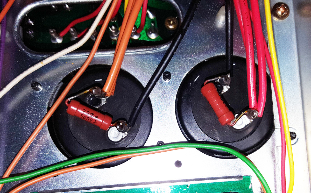
read the DC voltage at the terminals of each of the 2 big caps. Right across the red bleeder resistors 560 ohms and 2 watts.
then read the AC voltage at those same two points. You may have to use a "dc blocking capacitor" if the meter doesn't have one.
That would be a 0.1uf or so film cap in series with the red probe's tip, so the DC voltage does not interfere with the AC voltage reading.
We are looking at the performance of the two big caps, 4700uf 35v dc.
Should show + and - 27 volts or so on DC
and we are looking for the AC voltages (ripple) to compare against each other.
Hum that is unaffected by any controls, in both channels, could be from this.
As for the work you did, think about this:
you left old capacitors and transistors in the audio path - possibly masking the improvements you DID make.
Have you seen this thread:
http://www.audiokarma.org/forums/in...x-535-noisy-transistors.809085/#post-11299995
Audiokarma, and a BIG Welcome to a fixer in training!!!.read the DC voltage at the terminals of each of the 2 big caps. Right across the red bleeder resistors 560 ohms and 2 watts.
then read the AC voltage at those same two points. You may have to use a "dc blocking capacitor" if the meter doesn't have one.
That would be a 0.1uf or so film cap in series with the red probe's tip, so the DC voltage does not interfere with the AC voltage reading.
We are looking at the performance of the two big caps, 4700uf 35v dc.
Should show + and - 27 volts or so on DC
and we are looking for the AC voltages (ripple) to compare against each other.
Hum that is unaffected by any controls, in both channels, could be from this.
As for the work you did, think about this:
you left old capacitors and transistors in the audio path - possibly masking the improvements you DID make.
Have you seen this thread:
http://www.audiokarma.org/forums/in...x-535-noisy-transistors.809085/#post-11299995
Natalya
New Member
The DC voltage was -27 for one, and 17.5 for the other, so that's out of spec. I didn't have a 0.1uf capacitor on hand so I didn't attempt the AC voltage.
Also, I finally took a video of the noise!
@Old capacitors & such left:
I finally replaced all the rest of the capacitors and some more transistors, this time on the Control board and the Equalizer board, so there shouldn't be any old stuff left aside from the super caps.
When I ordered those parts I didn't know there was an anomaly with the super caps so I haven't ordered new ones of those yet. There was a leaky cap on the EQ board, so I'm glad I got that replaced.
Any recommendations on super cap replacements? They have some similarly rated ones on Mouser but I don't want to accidentally get a kind that won't work properly.
Yes, that's been super helpful! That's the parts list I've used.
@Old capacitors & such left:
I finally replaced all the rest of the capacitors and some more transistors, this time on the Control board and the Equalizer board, so there shouldn't be any old stuff left aside from the super caps.
When I ordered those parts I didn't know there was an anomaly with the super caps so I haven't ordered new ones of those yet. There was a leaky cap on the EQ board, so I'm glad I got that replaced.
Any recommendations on super cap replacements? They have some similarly rated ones on Mouser but I don't want to accidentally get a kind that won't work properly.
Have you seen this thread:
http://www.audiokarma.org/forums/in...x-535-noisy-transistors.809085/#post-11299995
Yes, that's been super helpful! That's the parts list I've used.
UncleBingo
Super Member
"Supercapacitor" is an entirely different thing than the large main filters. It's semantic but clarity is important.
UncleBingo
Super Member
I typically up the capacitance value (not more than 2X) and then find a capacitor with equal or higher voltage rating that is a good mechanical fit for the clamps (Diameter). If they're soldered to a circuit board
the pin-spacing becomes critical.
the pin-spacing becomes critical.
Natalya
New Member
Okay the large ones are 35v electrolytic 4700uF. I found these on Mouser:
https://www.mouser.com/ProductDetail/United-Chemi-Con/EGPD350ELL752MM40H?qs=sGAEpiMZZMtZ1n0r9vR22UhSjrTM10DEMeoEy8g352UMIFj5yixFuQ==
35V 7500uF 20% Tolerance "High Temp" Electrolytic
Would these be a good choice, or should I look at something else? Their size is considerably smaller than the originals, but I think I could make them fit because they don't go into a circuit board.
There are also these Panasonics:
https://www.mouser.com/ProductDetail/Panasonic/EEU-HD1V682?qs=sGAEpiMZZMtZ1n0r9vR22QGha91sM8wW3OuajDd/hTg=
IDK if brand is important or not. 35V 6800uF 20% Tolerance "General Purpose" Electrolytic
Last edited:
Go UP in VOLTAGE to 50V. There's not a lot of headroom voltage wise on the 35V cap. With increase in Todays Line Voltage your Rail Voltages will be close to 35 (within 5V). Best to go to 50V or even 63V. Chances are the new cap will fit inside an old cap case. (Gut the case and run the leads thru the rubber gasket, seal the can case, and wrap the new leads around the old tabs on the bottom and solder in). No muss, No Fuss. And you won't have to mess with spacers, etc. This one will do just fine in the 535. https://www.mouser.com/ProductDetai...EpiMZZMtZ1n0r9vR22TZ4hs%2bw0LzJV%2bpaXgpFVfA=
UncleBingo
Super Member
I agree with Larry about upping the voltage, for sure. If this were a valuable tube receiver I would agree with re-stuffing the capacitor cans- in this case, I'd go with the capacitor that meets the specs that is the closest to the existing diameter and skip re-stuffing the cans.
Something like this: 647-LKG1J682MESBAK
or this: 647-LKG1J682MESCBK
Check the diameter of the caps in your receiver and use the one closest without going over, so it will fit inside the clamps. Some self adhesive cork works great for spanning the gap if the new caps are a little bit narrow.
Something like this: 647-LKG1J682MESBAK
or this: 647-LKG1J682MESCBK
Check the diameter of the caps in your receiver and use the one closest without going over, so it will fit inside the clamps. Some self adhesive cork works great for spanning the gap if the new caps are a little bit narrow.
Natalya
New Member
Hey I looked at the resistors in the photo at the top of the page, between the leads of the big caps, they say 560ohm but I don't know like their wattage? Anyway, with a multimeter they're not reading 560 ohms, one is around 530 the other is like 270. I think I need to replace those too. I'm guessing they're metal film, but I don't know how current works with them. I've seen some like really chunky huge 1ohm resistors or like a tiny small 1M ohm resistor before.
If you haven't lifted one end of each resistor, it's likely that the measured resistance is not accurate.Hey I looked at the resistors in the photo at the top of the page, between the leads of the big caps, they say 560ohm but I don't know like their wattage? Anyway, with a multimeter they're not reading 560 ohms, one is around 530 the other is like 270. I think I need to replace those too. I'm guessing they're metal film, but I don't know how current works with them. I've seen some like really chunky huge 1ohm resistors or like a tiny small 1M ohm resistor before.
If they measure bad after lifting one end, you will need to replace with 560 ohm, 2 W, 5% metal oxide film resistors as per the service manual.
Last edited:
Watthour
Electron Rancher - JS3600
Incidentally, consider the tolerance of a component when testing. A resistor rated at 560Ω with a 10% tolerance would be considered acceptable with an actual resistance value between 504 and 616Ω. As LesE alluded, testing in-circuit can quickly reveal shorts, but for value testing the component should be isolated from the circuit (at least one lead lifted). Chances are the bleeder resistors are just fine.
Natalya
New Member
I agree with Larry about upping the voltage, for sure. If this were a valuable tube receiver I would agree with re-stuffing the capacitor cans- in this case, I'd go with the capacitor that meets the specs that is the closest to the existing diameter and skip re-stuffing the cans.
Something like this: 647-LKG1J682MESBAK
or this: 647-LKG1J682MESCBK
Check the diameter of the caps in your receiver and use the one closest without going over, so it will fit inside the clamps. Some self adhesive cork works great for spanning the gap if the new caps are a little bit narrow.
All right, I measured the diameter, they were 35mm. I therefore went with the 2nd caps you listed and got them in the mail a couple days ago. Anything I need to watch out for when installing them? I've never worked with capacitors this big.
Y'all were right about the bleeder resisters, I lifted one end from each of them and they read at about 560 ohms as specified.
dly66
Super Member
Not very complicated. Usually good to unscrew the screws holding the clamp to the chassis so you can unscrew the horizontal screw that lets the clamp grab the side of the capacitor. If the capacitor and clamp match the capacitor should not slide in the clamp. Otherwise keep the orientation and connections straight when hooking back up, especially the polarity of the cap. The two big caps are across the high voltage power rails to the amp circuit. Most modern capacitors have short pins I have soldered butt connectors (plastic cover removed if insulated), bent section of 12 ga solid wire I have a spool around, or other means to give more length to solder wires to. If the clamp does not grap adhesive cork was mentioned above but if you are near a Hobby Lobby I have gotten thin foam sheets back in the craft section for about a $1 and cut out a band to put between the clamp and capacitor to help hold the cap.
The bleed resistors will discharge the capacitors when it powers off. Some manufacturers don't use them so the higher the capacitance and the higher the operating voltage the bigger zap they have stored. I put a filter cap out of a Yamaha CA-610II on my $20 transistor, cap, etc tester and it was charged did not zap me in the removal process but my tester lit up like the start button was pushed and only gave garbage readings after that. Lesson learned and new one had to be acquired. Clipping a higher resistance higher power resistors (say 300 ohm 5 watt) can bleed any residual charge on big caps.
Welcome to AK and ownership of the SX-535. I used MarktheFixer's lists on the one that was my first restoration project and still have it in my collection. It was an as-is auction unit that basically sounded like it had a head cold - no sparkle severely lacking on the highs - especially with fm. Recapping and replacing the transistors on the bad 11 list (had 5 types in 16 positions) it sounded good when finished. Solidly built and nice blue display.


UncleBingo
Super Member
All right, I measured the diameter, they were 35mm. I therefore went with the 2nd caps you listed and got them in the mail a couple days ago. Anything I need to watch out for when installing them? I've never worked with capacitors this big.
Y'all were right about the bleeder resisters, I lifted one end from each of them and they read at about 560 ohms as specified.
It's like real-estate only "Polarity, polarity, polarity".
I take pictures and pull them out one at a time and triple check everything. If I have to leave the repair, I also label the wires + or - using masking tapes.
people aren't joking when they call them firecrackers. I only blew up 1 cap a long time ago. it was a small cap and I about capped my pants if you take my meaning.
dly66
Super Member
people aren't joking when they call them firecrackers.
I have had a 3.3 uF 50V one blow one time. Had recapped the amp board and had just brought it up on a dim bulb tester. Can and guts went flying just the metal parts soldered to the board remained. Takes your breath away, basically like a gun going off at close range. Other than the cap fortunately no other damage to the board.
Natalya
New Member
Okay I did the filter caps.
SOME GOOD SOME BAD
Good:
- No more buzzing noise! It's gone! The noise was there the second one turned on the stereo, now it is totally absent. Yay!
Bad:
- I turned it on with the bottom still removed and the lid removed so I could see if anything funny was going to happen.
- I had dial set to FM, volume turned to 0
- I heard a faint bubbling noise? It was from a component, not sure which one, probably one of the new big caps. If you know what an electric tea kettle sounds like before it starts to boil, it sounded like that but MUCH quieter
- It sounded like it was coming from one of the new capacitors
- I quickly turned it off to isolate the problem
- I took my multimeter, set to DC, put it across the leads of one filter cap (one with red wires), turned it on, it ramped up to 27 volts after a few seconds.
- Faint tea kettle sound started to return so I turned it off again
- Put multimeter on the other filter cap (one with orange wires), turned it on, voltage went up, started to hear the noise, and then a small pop -- two fuses blew
- These were the two 4A fuses on the power board
- ALSO I noticed that one of the filter caps, the one with the orange wires, upon touching it felt hot.
- I checked the polarity multiple times, it looks correct for the big filter caps. Assuming a minus sign means ground and black wire means ground I have them wired properly.
I can check the electrical diagram, but not sure what to look for. I'm suspecting a short somewhere.
It was NOT blowing those fuses before switching the filter caps. So maybe I did the procedure wrong?
Last edited:
Similar threads
- Replies
- 9
- Views
- 543
- Replies
- 0
- Views
- 154