SX 780 and intermittent operation

Chevelle70

New Member
Hello-

I just picked up a SX 780 from the original owner this week, after it had been setting for 30 years. He had it inside a cabinet so water is not an issue. Looks almost perfect! When we turned it on it wouldn't produce any sound. After poking buttons on and off a few times, we got FM side to work on A speakers but did not test B side.

Once I got it home, I can't get any sound, FM/AM AUX (have not tried phono). All the lights work. On initial inspection I noticed the power meter on right side, fluctuating like it's working but the volume was erratic-Barely turning volume up got fairly loud, continuing to turn volume up there was a decrease, then it picked back up again.

I took it over to a repair shop locally. They are afraid the darlington packs are on the way out. I have not checked anything else yet, I'm not well versed in electronic repairs but willing to learn. I'm going to look for a service manual online as well.

Any reccomendations? Thanks!
 

Attachments

  • pioneer.JPG
    pioneer.JPG
    99.8 KB · Views: 18
Service manual can be downloaded from hifiengine.com. Free registration needed to download. One ot the most prominent failures of the SX-780 is bad solder connections in the power supply section. Q19, Q20 and Q25 run hot. Resolder their leads. Bigger heatsinks is a good idea, especially Q25. See attached picture with transistors inside purple/green box in lower left quadrant.
SX-780Top10 - power.jpg

Check out this thread for a great way to get rid of troublesome STK modules with a discrete repairable circuit: http://audiokarma.org/forums/index.php?threads/stk-0050-replacement-for-sx-780-and-others.721181/ It is a long thread but they work great, I have used them myself.
 
Dirty controls and/or bad solder connections. I sincerely doubt the Darlingtons are “on their way out.”
 
These symptoms can also indicate bad contacts in the Protection circuit relay, with relay replacement being the best option. Burnishing or deoxit is rarely a long term fix for a bad relay.
 
I've seen 780's with SELF De-Soldered Diodes in the Power supply also. And with burned traces, along with the usual suspects of the Voltage Regulator transistors having either cold solder joints or Self De-Soldered joints. Replace the diodes with 1n4006 and 1n5406 diodes, and lift them OFF the BOARD by 1/4"-3/8". Also the Voltage Regulators should be replaced with
OLD.................NEW

Regulators........................................................TO-126 Plastic..............TO-220
Q19 2sd325R............................................... 512-KSC2073TU or 863-MJE15032G (*)
Q20 2sb536L................................................ 512-KSA940TU or 863-MJE15033G (*)
Q25 2SD712..................................................512-KSC2073TU or 863-MJE15032G (*)
(*)MJE's are complete overkill to Handle Heat better. Need bigger Heatsinks tho as they are TO220 vs. TO-126. Or Drill and Tap the WALL HEATSINK and Remote Mount them on the Wall Heatsink

ISOLATION KIT for Heatsink
532-4880MG with mica insulator, screw, washer, lock washer, insulating shoulder washer & nut. You need 3.
534-4672 to-220 mica insulators $0.12 each
get a few extra mica's, it's cheap insurance.

The rest of them
Transistor list
Q7/Q8 2sa726. Repl with KSA992. Replace when found pre-emptively.

q11 2sc1775 ................................................ 512-KSC1845FTA
q12 2sc1775................................................. 512-KSC1845FTA
q13 2sc1885................................................. 512-KSC2383YTA
q14 2sc1885................................................. 512-KSC2383YTA
q15 2sa912................................................... 512-KSA1013YBU
q16 2sa912................................................... 512-KSA1013YB
q26 2sc1384.......................................................512-KSC2690A

NEW RELAY
SX-780 (for protect) 4pdt pcb mount....................... 653-my4-02-dc48
 
Thank you everyone for all the info!! I'll admit this is above my head but will do some reading and see if I can work with the tech. Sure hope it's nothing too bad.
 
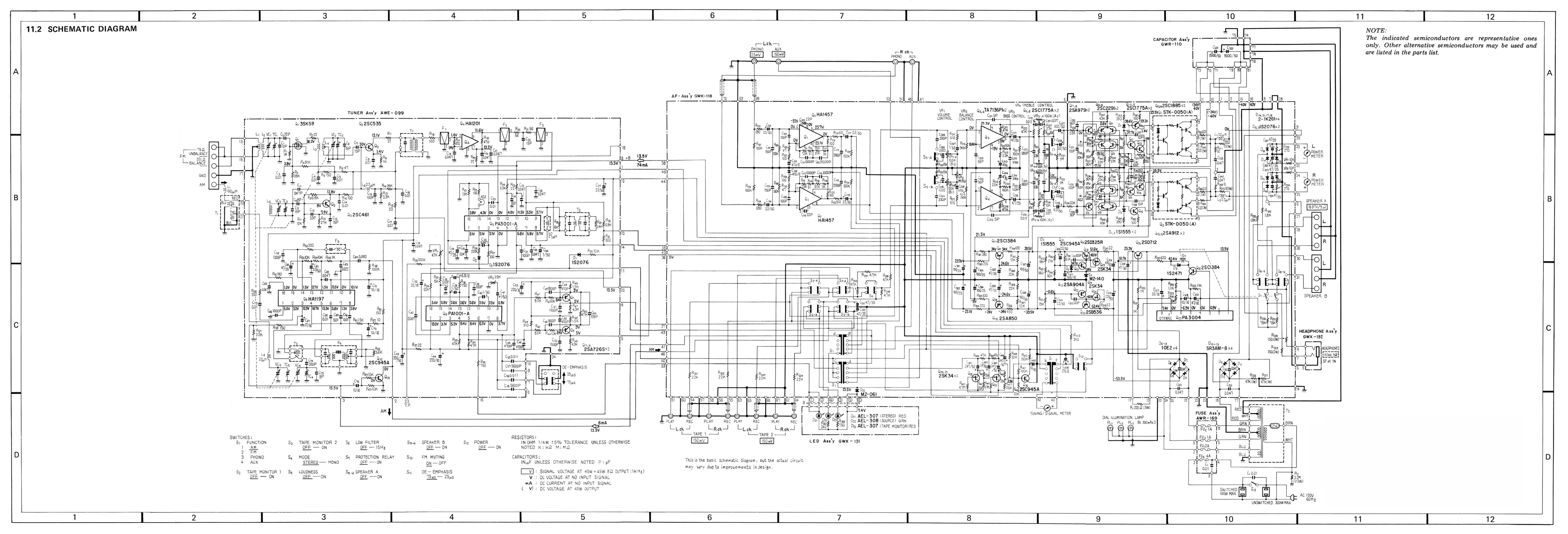
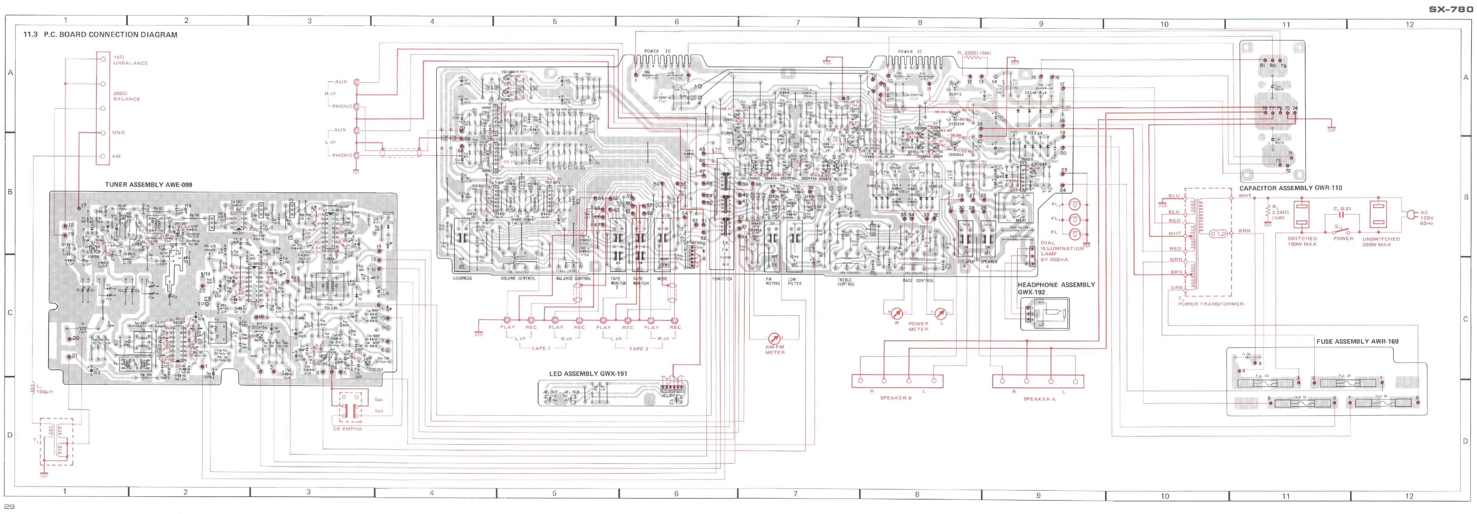
Save the jpgs below and take them to Office Depot and have them blow them up to 24x36" (Cost about $3.00 ea.). Thanks to WATTHOUR, these are probably the best 780 schematic and board layout out there. If you have to take it back to the tech, copy this thread and the schematics and ask him to read the thread for ideas. There are some threads in here that deal with the 780 packs as far as how to test them, and there is one that is a breakthrough for replacing the packs with individual components (you have to buy the new boards, heatsink, and parts, assemble them.) which improves longevity, and safety of the unit. l should point out that most all of the part #'s listed above are Mouser #'s.


SX-780PCBoardLayout.jpg
SX-780 schematic WIDE.jpg
 
Last edited:
If you want the original, full-size versions, they are here (linking them seems to be shrinking them):

PioneerSX-780SchematicWide.jpg


SX-780PCBoardLayout.jpg
 
Save the jpgs below and take them to Office Depot and have them blow them up to 24x36" (Cost about $3.00 ea.). Thanks to WATTHOUR, these are probably the best 780 schematic and board layout out there. If you have to take it back to the tech, copy this thread and the schematics and ask him to read the thread for ideas. There are some threads in here that deal with the 780 packs as far as how to test them, and there is one that is a breakthrough for replacing the packs with individual components (you have to buy the new boards, heatsink, and parts, assemble them.) which improves longevity, and safety of the unit. l should point out that most all of the part #'s listed above are Mouser #'s.


View attachment 1434673
View attachment 1434675

Thanks for all the info! I'll get these printed out tomorrow and stop in the shop. Wish I knew enough to tackle some of this but I don't.

Can't help but think the problem isn't too big as I had sound from it for a few mins before it stopped. And it was dusty inside looking through the top louvered section.
 
If this receiver has been sitting for 30 years, the volume control is probably dirty/corroded and that might be interfering with sound output. You mentioned the power meter on that side is working but no or low sound. I'd suggest a good cleaning of the pots and switches (all of them) with some Deoxit and see if that doesn't resolve the issue. Always try easy/cheap first. I'd start here: https://audiokarma.org/forums/index.php?threads/the-idiots-guide-to-using-deoxit-revisited.207005/
 
If this receiver has been sitting for 30 years, the volume control is probably dirty/corroded and that might be interfering with sound output. You mentioned the power meter on that side is working but no or low sound. I'd suggest a good cleaning of the pots and switches (all of them) with some Deoxit and see if that doesn't resolve the issue. Always try easy/cheap first. I'd start here: https://audiokarma.org/forums/index.php?threads/the-idiots-guide-to-using-deoxit-revisited.207005/
I made a new version of this guide too :) :
https://audiokarma.org/forums/index.php?threads/tldr-deoxit-guide.850968/
 
Wish me luck. I picked the receiver back up from the shop and told him I wanted to try and clean it up myself and see what I could get working. They seem to think it was still the power modules inside the unit and that it would be too costly to repair.

I brought it home and actually got it to produce sound on both the FM and the auxiliary input however only the right hand side speaker , on either A or B are working. Left side speakers either on A or B side does not produce any sound.

The volume is very erratic barely any turning of the knob and the volume should skyhigh. The further you turn the knob it seems to settle down and go into more of a controlled increase. So I’m assuming that is dirty.

Turning the balance knob only shuts the speakers off if they are both connected to speaker A or B Turing balance to the left side. Sound comes back in once it is in the middle or goes to the right for balance.

I’m going to follow the guide above and start tearing it apart and using de-oxit on whatever I can find. Thank you for all your help and if you have any suggestions I’m all ears
 
So I got everything cleaned up in the volume knob no longer has the erratic issues. It starts off very low and gradually increases and sounds actually very nice. I still do not have any power on the one side with the left speakers either on channel a or channel B. I did take all of the fuses out and replace them and that did not change anything.

On the volume meters only the right hand side shows power or measures power I should say the left-hand side appears to have no power at all plus no sound. What should I be checking next?
 
There is a protection circuit in the receiver, there to protect the speakers from failed output devices and to protect output devices from failing speakers, although it is not so effective against the latter considering the hybrid output modules.

Nonetheless, if one of the output modules has failed in the traditional mode (shorted), the protection relay would not close, the there would be no sound from either channel. The current indications are that you do not have a shorted output module, and we can (temporarily) presume that a channel is missing somewhere.

The first thing is to verify the source. In addition to broadcast radio, the unit should be operated with some source other than radio, and that source should be alternately tried in both the AUX inputs and TAPE inputs to eliminate some other potential problems. A CD player, MP3 player, a different receiver with pre-amp outputs, or other such device can be used to input a source to the SX-780. With such a signal source, we can attempt to eliminate the various mode switches and TAPE MON switches (all of which are suspect) and then move along to tracing the signal through the amplifier stages. Ideally, a second receiver with a per-amp output and main amp input set of RCA jacks would be available along with a pair of RCA cables, allowing us to test multiple paths and eliminate multiple potential problems.

Do you have something to connect to the inputs other than a turntable?
 
You can check DC bias voltages between channels and the schematic
You can make a small probe with a 1uF film or NP ecap in series to block DC, use to access points and bring them to another good working pre-amp AUX input (RCA plug) as a way to monitor the signal flow.
 
I’ve been testing with my IPhone using audio ran through input - I’ll try the other inputs as well. I also have a tape player - will try that.

Fm and Am signals work and produce same results

I did get enough nerve up to test the Darlington packs with multi meter - I came up with following :

Power pack closest to on/off switch:
(1) 13.1
(2) 40.8
(3-8) 0 each terminal
(9) 40.8
(0) 15.8

Alternate pack
(1) -01.1
(2) -40.7
(3-8) 0 each terminal
(9) -40.8
(0) 01.3

I haven’t slughtest idea what this all means but?????
 
The output module closest to the power switch (left end of the chassis) drives the left channel speakers, and the other is (obviously) the right channel. 13-15V on pins 1 and 0 of the power pack is not a good sign. It may be time to desolder the power pack leads and get them off the circuit board for a little more testing.
 
The output module closest to the power switch (left end of the chassis) drives the left channel speakers, and the other is (obviously) the right channel. 13-15V on pins 1 and 0 of the power pack is not a good sign. It may be time to desolder the power pack leads and get them off the circuit board for a little more testing.

Oh boy. Ok just remove the left power pack?

And this is pretty in-depth for me-but can I just use a soldering iron and warm up each pin area to remove the old pack?
 
Back
Top Bottom