Trouble Shooting Power Amp SX-1050

micwood55

Active Member
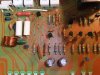
Hello everyone, Thought I would start this thread instead of jumping in on other topics.. Sorry about that new too Audio restoration and Forums in general. I hate not knowing or asking for help! But this Power Amp Board is really complex too bad Diagram looks so different from foil side learning at my age is getting harder. I started with a working Unit and wanted to recap it to be safe. Couple issues need fixing like bad phono jack channel and no tuner signal meters working. Started off with replacing Output Transistors and recapping Board thought I would clean up some bad looking solder joints and maybe over heated the VR1. Stuck now with a bad board what's the proper way to trouble shoot this problem. I am burning R34 & R35 Lifted all top resistors today the 2 Watt resistors all checked out OK I think my problem is Left Side with possibly trimmer and need to replace them if Transistors check out good tomorrow any help would be appreciated I might be over my head with this one just throwing money at it now. Tools and more parts now Need part Numbers for right (Bourns) Trimmers
Thanks Mike
 

Attachments

  • DSCF6731.JPG
    DSCF6731.JPG
    140.2 KB · Views: 82
  • DSCF6732.JPG
    DSCF6732.JPG
    129.6 KB · Views: 75
  • DSCF6718.JPG
    DSCF6718.JPG
    111.2 KB · Views: 82
  • DSCF6719.JPG
    DSCF6719.JPG
    120.8 KB · Views: 81
  • DSCF6729.JPG
    DSCF6729.JPG
    92.1 KB · Views: 81
  • DSCF6730.JPG
    DSCF6730.JPG
    129.5 KB · Views: 78
So you recaped it and now it doesn't work?
Was there any point in the last steps you did when you checked for operation?
Are you using or have a DBT (Dim Bulb Tester) on hand?
What recap list are you using?
Note:
Some replacement (Equivalent) transistors do not share the same leg placement as the originals. Check the Data sheets.
 
Thank you for your quick response, any help here is appreciated also being new at this I read a lot before and practice on my 780 which came out nice, So onto the 1050... This unit is crazy complicated man and I know now that it's my fault anyways the First step replaced all outputs and recapped amp board not much there right. read on another web site to cleanup solder on this board, Forgetting how old everything is big mistake for a beginner, Started cleaning up some solder joints and then stopped was worried about the heat with the crap tool I was using, but now own a soldering station so I can watch my temp. Put it back together and blew 10 amp fuse! thought I saw a flash from board but I'm getting old and need new damn glasses LOL
Removed Outputs and found a shorted PNP which now I believe it blew because of board issue. Mouser was nice enough to send me another no charge. Funny but last night was reading another thread about DC offset going very wrong and it just hit me how to understand this damn Diagram. I wasn't sure if it was safe or proper too but did not want too damage my new outputs so tried turning unit on with them disconnected to see if relays clicked after replacing fuse, Then I saw R43 & 47 Burn. I'm a retired Auto Tech and specialized in Imports so I know how confusing Japanese manuals and diagrams are but this is hand written and parts are not that easy to just lookup. Don't have a DBT but need one if going to continue on to my 980... Never thought I would screw up right off the bat maybe it's a good thing put the brakes on and will be more careful further down the road on control board that would be a bummer not trying to rush have bad back so can only work for few hours before needing break. I bought a SCR Tester money is tight and this think is sucking it up I.m way over 200$ now on parts and tools. I think Transistor Q11, Q21 are right on this circuit so going to check them right now tested all Diode with meter on board but did not lift leg yet everything breaks if I had more part numbers for parts like VR1,VR3 proper replacement resistors and diodes would be braver... lifted legs on all the 10 Ohm 2 (W) Resistors yesterday now need 2 the metal ones should they be upgraded? There should be more threads on Restoration and Newbies LOL
Just ask and you'll receive! right
 
Transistor Q11 is bad so going to replace all... Be careful touching up old solder joints unless you plan on replacing Transistors? Also as a Beginner learned better protect or cover up boards when working on another very close to it. Specially if you need a tool to remove old part? De-soldering sucks with out De-soldering gun we get bye and this makes it worth while 1,550$ for 1050

http://www.ebay.com/itm/161865263924?_trksid=p2055119.m1438.l2649&ssPageName=STRK:MEBIDX:IT
 
Last edited:
I WILL LIST ALL PARTS REPLACED PERTAINING TO MY ISSUES ON BOARD
power amp board
awh-047 q1 2sa750 0 0 0 0 0 512-KSA992FBU
awh-047 q2 2sa750 0 0 0 0 0 512-KSA992FBU
awh-047 q3 2sa750 0 0 0 0 0 512-KSA992FBU
awh-047 q4 2sa750 0 0 0 0 0 512-KSA992FBU
awh-047 q5 2sa750 0 0 0 0 0 512-KSA992FBU
awh-047 q6 2sa750 0 0 0 0 0 512-KSA992FBU (6)
awh-047 q7 2sc1439 0 0 0 0 0 512-KSC3503dstu
awh-047 q8 2sc1439 0 0 0 0 0 512-KSC3503dstu
awh-047 q9 2sc1439 0 0 0 0 0 512-KSC3503dstu
awh-047 q10 2sc1439 0 0 0 0 0 512-KSC3503dstu (4)
awh-047 q11 2sa858 0 0 0 0 0 512-KSA1381ESTU
awh-047 q12 2sa858 0 0 0 0 0 512-KSA1381ESTU
awh-047 q13 2sa858 0 0 0 0 0 512-KSA1381ESTU
awh-047 q14 2sa858 0 0 0 0 0 512-KSA1381ESTU (4)
awh-047 q15 2sc1439 0 0 0 0 0 512-KSC3503dstu
awh-047 q16 2sc1439 0 0 0 0 0 512-KSC3503dstu (2)
awh-047 q17 2sb536a 0 0 0 0 0 512-KSA940TU
awh-047 q18 2sb536a 0 0 0 0 0 512-KSA940TU (2)
awh-047 q19 2sd381a 0 0 0 0 0 512-KSC2073TU
awh-047 q20 2sd381a 0 0 0 0 0 512-KSC2073TU (2)
awh-047 q21 2sa858 0 0 0 0 0 512-KSA1381ESTU
awh-047 q22 2sa858 0 0 0 0 0 512-KSA1381ESTU (2)
Main Outputs
awh-047 q23 2sb539c 0 0 0 0 0 863-MJ21193G
awh-047 q24 2sb539c 0 0 0 0 0 863-MJ21193G
awh-047 q25 2sd287c 0 0 0 0 0 863-MJ21194G
awh-047 q26 2sd287c 0 0 0 0 0 863-MJ21194G
awh-047 q27 2sb539c 0 0 0 0 0 863-MJ21193G
awh-047 q28 2sb539c 0 0 0 0 0 863-MJ21193G
awh-047 q29 2sd287c 0 0 0 0 0 863-MJ21194G
awh-047 q30 2sd287c 0 0 0 0 0 863-MJ21194G (8)
Help from Markthefixer with parts and others

652-3386H-1-501LF 500ohms 3386H Single Turn 3/8" ? 10% parallel to pcb
sx-1050 idle current adjust

652-3296P-1-202LF 2Kohms 3296P Multi Turn : 12 3/8" Sealed parallel to pcb
SX-1050 offset voltage adjust
 
Last edited:
Are you using a DBT???????????????????
This tool will save you (Lots) money and time.

The transistors I can see, look like their installed correctly. Some I can not confirm. I noticed you left the Sanyo robin egg caps in C2 and C1 (Small issue for now, get the set running first). If you can take a few more images of the big driver transistors would help. The ones on the board near the top closest to the heatsink transistors. They are mounted to the small bent heatsinks mounted to the board it self.
What 10 amp fuse?
Check the install of the big outputs you changed.
Did you use the non-conductive paste?
The outside case of the big outputs is part of the circuit (The Collector) and needs to be insulated from the heatsink. Check to see if they are shorted to the heatsink. Improper install can cause a fuse to blow as well as the wrong paste. The mica insulators are required.
When you dissemble them, check how the socket's fit to the heatsink and keep in mind, (They; the outputs - can't touch any part of the heatsink).
Recheck all the outputs before you reinstall them.
I think you can run this amp with the outputs disconnected from the amp board. I don't see a feed back circuit but I am learning as well.
Be really careful of the STV diodes that are mounted to the heatsink, they are easy to damage when thrashing about. The wires are hair thin. If one wire breaks without notice it will cause havoc allowing the big outputs to go full throttle and fail.
VR3 and 4 are the trimmers for the idles. Turn them CCW's for now. You'll set them up later once you get the set from shorting out.
We like to gain match Q1 through 4. This makes the amp balance better (easier)
It's good that you are only messing with the single board?
I want to mention in hindsight you should of posted your intentions before you started this 1050. I know you had success on the 750 but this is a little more of a machine. No matter, you are learning something new and adding to an already seasoned skill.

Did I mention:
Are you using a DBT???????????????????
This tool will save you (Lots) money and time.
 
Last edited:
Thanks zebulon1 for the help and advise very appreciated. This Receiver is very complicated for a beginner and I now need to buy a DBT but living on SS so have to wait until the 3rd I am lucky to have a sx-980 as backup that also needs repair. I wanted to replace those blue and green caps but can't find anything on mouser that match up the green caps read 39.70 nF? If you have a recommendation going to order all Transistors, Trimmers. Diodes tested good with scr tester but did not lift leg? I don't feel confident when ordering parts... Right part numbers would replace them too, Markthefixer helped me out with trimmer # I hope this thread can help the next newbie who wants too try recapping and decides to touch up solder joints on this board beware of the heat on these 35 year old parts. I always go the easy route thought replace Outputs first then test. The 10 amp fuse was on the bottom blew right after touching up solder on board and blew 1 new PNP Transistor. Yesterday I removed Transistors on that circuit and Q11 was bad was given this part list from WE6C going to order all Trans for unit to have on hand as I move on of course after I fix this board issue. Now if I try to power this unit up for just a split second the surge protector gets super hot (Smokes) and relays don't click but if I disconnect Outputs, Unit will light up, Relays click but resistors burn. I did replace all Insulators and bought recommended heat paste link blow didn't help so decided to lift most resistors they checked out OK. going to try and makes this my last order from mouser if possible, Any recommendation on problem parts with replacement part # are appreciated
http://www.mouser.com/ProductDetail...GAEpiMZZMvJqaFk9BIiv4QH%2bcOw0u9jlbkE1zTJkxs=
 
Pics of new Outputs and Insulators with recommended Paste link above
All checking out good no shorts
 

Attachments

  • DSCF6733.JPG
    DSCF6733.JPG
    89.8 KB · Views: 47
  • DSCF6734.JPG
    DSCF6734.JPG
    85.2 KB · Views: 38
  • DSCF6737.JPG
    DSCF6737.JPG
    97.8 KB · Views: 37
  • DSCF6738.JPG
    DSCF6738.JPG
    81.6 KB · Views: 35
  • DSCF6739.JPG
    DSCF6739.JPG
    91.4 KB · Views: 40
  • DSCF6735.JPG
    DSCF6735.JPG
    84.5 KB · Views: 35
  • DSCF6736.JPG
    DSCF6736.JPG
    87.9 KB · Views: 34
Replace both Q11 and Q21. Double check the leg placement. Q21 could of caused the toasting resistors by shorting out Q11.
I'm worried that a big output is shorted.
You have to know you caused this. Go over everything matching the legs with the schematic making sure the emitter goes to the proper point and so on. I don't remember any issue with the board print on the 1050's but just be meticulous. Double check everything! Look for solder bridges and broken/damaged traces

Look up on how to build and use a DBT. As well as I know you in this post, you have all the components needed in the garage. A 100 watt incandescent bulb will work good for the 1050.
Make this the very next project and don't start back on the set until you get it completed.
Once you get it finished We'll help you understand it's use. In short (No pun intended) it draws the current from the set if the set has a short circuit. Saves outputs, fuses and prevents magic smoke from appearing.
I'm glad you posted, enjoy the experience, we've all been there. Me more than most!
 
Last edited:
OK I NOW KNOW WHAT A DBT IS AND HOW TO USE ONE "FEEL PRETTY STUPID"
GOING TO MAKE ONE MYSELF FOUND EXCELLENT VIDEO ON YOUTUBE...
FOR ALL NEWBIES DON'T TURN ON UNIT AFTER REPAIR WITH OUT USING ONE THESE OR SPEND CRAZY MONEY LIKE ME
 
Replace both Q11 and Q21. Double check the leg placement. Q21 could of caused the toasting resistors by shorting out Q11.
I'm worried that a big output is shorted.
You have to know you caused this. Go over everything matching the legs with the schematic making sure the emitter goes to the proper point and so on. I don't remember any issue with the board print on the 1050's but just be meticulous. Double check everything! Look for solder bridges and broken/damaged traces

Look up on how to build and use a DBT. As well as I know you in this post, you have all the components needed in the garage. A 100 watt incandescent bulb will work good for the 1050.
Make this the very next project and don't start back on the set until you get it completed.
Once you get it finished We'll help you understand it's use. In short (No pun intended) it draws the current from the set if the set has a short circuit. Saves outputs, fuses and prevents magic smoke from appearing.
I'm glad you posted, enjoy the experience, we've all been there. Me more than most!
OK I NOW KNOW WHAT A DBT IS AND HOW TO USE ONE "FEEL PRETTY STUPID"
GOING TO MAKE ONE MYSELF FOUND EXCELLENT VIDEO ON YOUTUBE...
FOR ALL NEWBIES DON'T TURN ON UNIT AFTER REPAIR WITH OUT USING ONE THESE OR SPEND CRAZY MONEY LIKE ME
 
I am working on the amp board of a SX-1050 right now too. Powered it up on a DBT and the bulb stayed bright, not good but didn't blow anything out. Turned out that one of the output transistor was shorted to ground. I used a silicone insulator (Tgard 220 series) that I am now questioning my choice of. Also the KSA1381ESTU and the KSC3503DSTU transistors are a bigger package transistor (TO-126) so I had to very carefully open up the holes on the board to accept the larger legs of these.
 
I am working on the amp board of a SX-1050 right now too. Powered it up on a DBT and the bulb stayed bright, not good but didn't blow anything out. Turned out that one of the output transistor was shorted to ground. I used a silicone insulator (Tgard 220 series) that I am now questioning my choice of. Also the KSA1381ESTU and the KSC3503DSTU transistors are a bigger package transistor (TO-126) so I had to very carefully open up the holes on the board to accept the larger legs of these.

Sounds like you know what your doing, Did you powered up your unit with outputs disconnected using your DBT? only asking because I wasn't sure if that was a safe way of testing output issue? I needed to eliminate the board and outputs trying to find cause of my fuse that blew. Now after finding out what one was and did feel a little stupid. Such a simple way too protect your Investment. I was using 3M cold fusion that was suppose to be OK but after burning up resistors decided to replace the mica Insulators and buy recommended paste the Insulators are only 13 cents just was lazy, Not wanting to look up part numbers or ask for help... for me that's the hardest thing getting the right parts. I have had 4 shipments for this unit @ 8.99 a pop starts getting expensive. Going to build my DBT today... keep me up to date on how your doing and add your issues with pics you will get help pretty quick here and help the next newbie also sounds really interesting how much more watts do you gain or does it just run cooler?
 
Last edited:
I am working on the amp board of a SX-1050 right now too. Powered it up on a DBT and the bulb stayed bright, not good but didn't blow anything out. Turned out that one of the output transistor was shorted to ground. I used a silicone insulator (Tgard 220 series) that I am now questioning my choice of. Also the KSA1381ESTU and the KSC3503DSTU transistors are a bigger package transistor (TO-126) so I had to very carefully open up the holes on the board to accept the larger legs of these.
I also had had one bad PNP out of box or it blew because of board or bad insulator. just getting the harness to connect to output can be tricky but after taking apart several times got good at it. I was really gentle doing it. Did you hit any snags with the bigger legs or change the harnesses too?
 
Are you using a DBT???????????????????
This tool will save you (Lots) money and time.

The transistors I can see, look like their installed correctly. Some I can not confirm. I noticed you left the Sanyo robin egg caps in C2 and C1 (Small issue for now, get the set running first). If you can take a few more images of the big driver transistors would help. The ones on the board near the top closest to the heatsink transistors. They are mounted to the small bent heatsinks mounted to the board it self.
What 10 amp fuse?
Check the install of the big outputs you changed.
Did you use the non-conductive paste?
The outside case of the big outputs is part of the circuit (The Collector) and needs to be insulated from the heatsink. Check to see if they are shorted to the heatsink. Improper install can cause a fuse to blow as well as the wrong paste. The mica insulators are required.
When you dissemble them, check how the socket's fit to the heatsink and keep in mind, (They; the outputs - can't touch any part of the heatsink).
Recheck all the outputs before you reinstall them.
I think you can run this amp with the outputs disconnected from the amp board. I don't see a feed back circuit but I am learning as well.
Be really careful of the STV diodes that are mounted to the heatsink, they are easy to damage when thrashing about. The wires are hair thin. If one wire breaks without notice it will cause havoc allowing the big outputs to go full throttle and fail.
VR3 and 4 are the trimmers for the idles. Turn them CCW's for now. You'll set them up later once you get the set from shorting out.
We like to gain match Q1 through 4. This makes the amp balance better (easier)
It's good that you are only messing with the single board?
I want to mention in hindsight you should of posted your intentions before you started this 1050. I know you had success on the 750 but this is a little more of a machine. No matter, you are learning something new and adding to an already seasoned skill.

Did I mention:
Are you using a DBT???????????????????
This tool will save you (Lots) money and time.
BUILDING ONE NOW!
 
Before I order parts again "Can someone help me out with these part # for 2 Diodes D3 & D4 small ones IS2473# one is right on my burnt circuit? Like to replace small caps Mylar 0.039 50V C13,C14,C23,C24 play it safe if I can get them. robin eggs C1 & C2 should be done too?
MAYBE THIS CAN BE MY LAST MOUSER ORDER FINGERS CROSSED
 
Last edited:
mylar caps don't need to be replaced.

diodes can be 1n4148

c1 c2 0.68uf 25v csza would benefit from being changed to 667-ECQ-E2684JF @ $0.62 ea
 
Hi micwood55. I am quite new at this to. I read all of the threads here to see what these other guys are doing and take the advise that they give.I have printed out every parts list that I find here. Because this is something that I want to do,I buy a lot of the cheaper parts in larger lots trying to build up an inventory. Cheaper buy the dozen. The only thing that I haven't got yet is the big filter caps $$$.
This amp board is a mirrored image split down the center so you can compare one side to the other, even the schematic is that way.
Right now my problem is that I can't get the DC balance set. The relay keeps kicking on and off and on one side even with the pot turn all the way to one side I can't get close to zero. I tried this with the output transistors connected and disconnected. Also with the pre amp to main amp jumpers in and out. I will leave these jumper out while working on a amp board just so I don't put any unwanted voltages to another board if I mess something up.
Right now I am going to rebuild the protection board just to make sure it isn't causing the problem and I was going to do it anyway.
 
Back
Top Bottom