Yamaha B2~ Should I repair the input board or do the bypass modification?

Nashou66

AK Subscriber
Subscriber
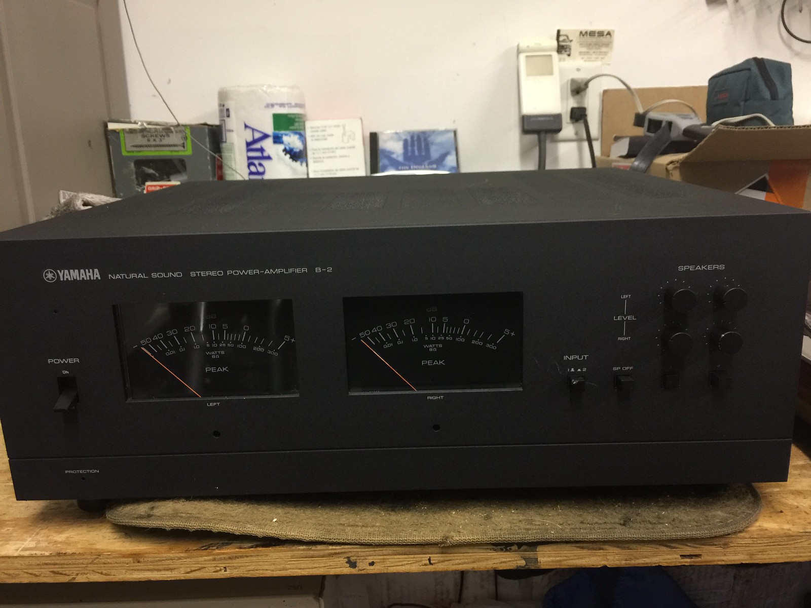
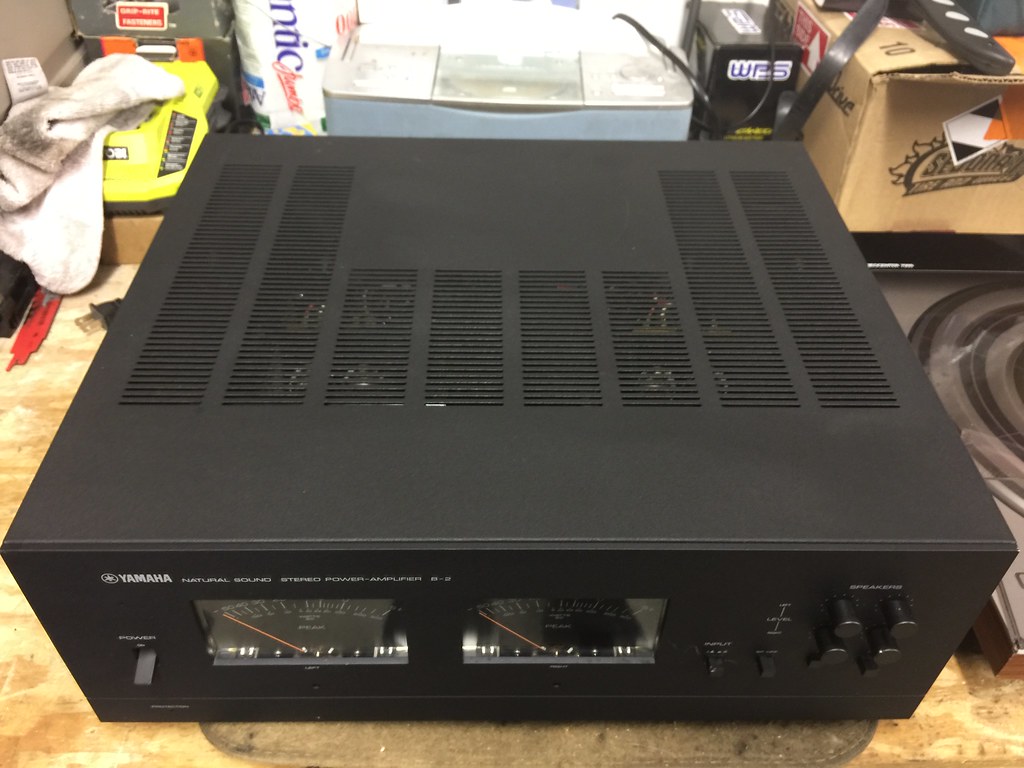
Hi Everyone, I just got in my possession a really clean B2 with a broken input board and switch.

I traded for this amp with a spare Sony G-90 CRT Projector i had and drove to Fond Du lac Wisconsin from Buffalo NY to deliver the projector and pick up the amp. Stoped at the Harley Davidson Museum as well :D

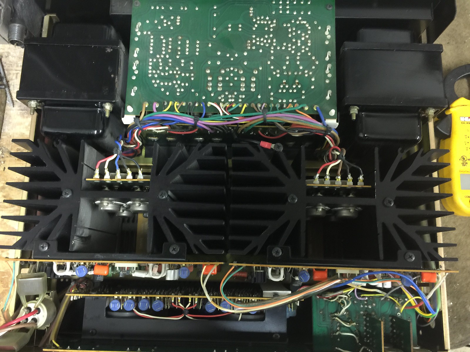
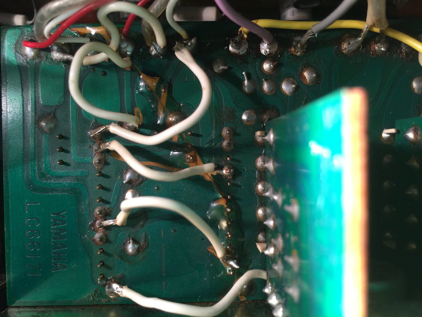
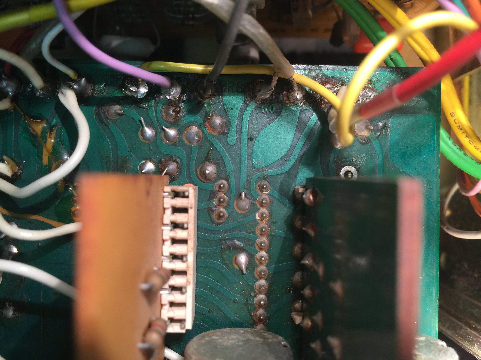
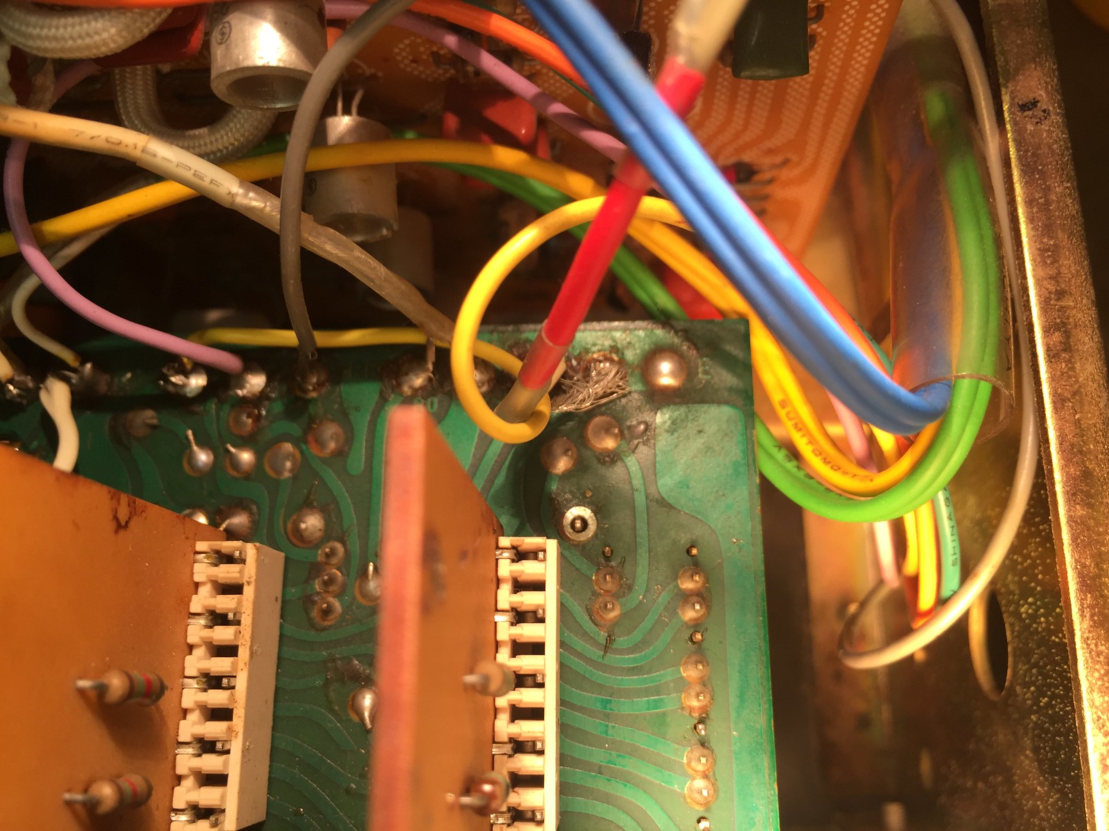
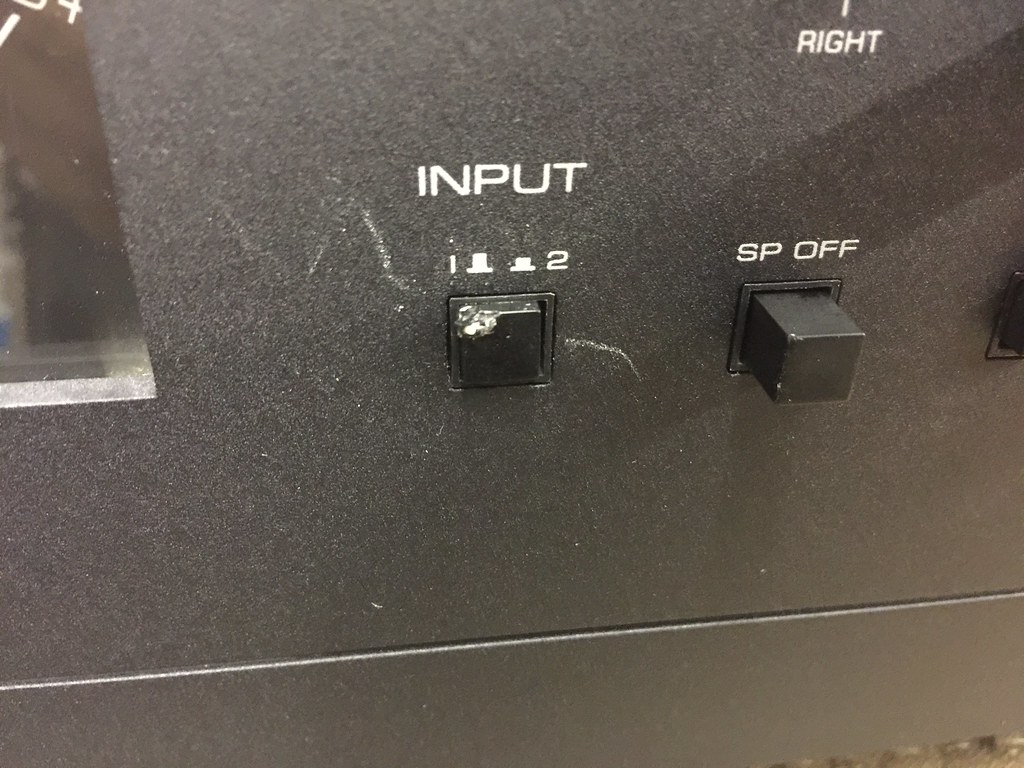
The input board looks to be cracked in a few spots and Jerry rigged with wires to get it to work. The Switch doesn't spring back and I it does nothing according to the seller. He said he got it from the previous owner who said it sat for over 20 years till recently. I was told it worked after he fiddled with the switch/Board.
I was thinking of making a new board with new switches since I have read that the originals are no longer
available. In the mean time I was going to do the direct input mod just to get it working while I work on designing the new input board . Or should I not make a new board and just go with the direct input mod?

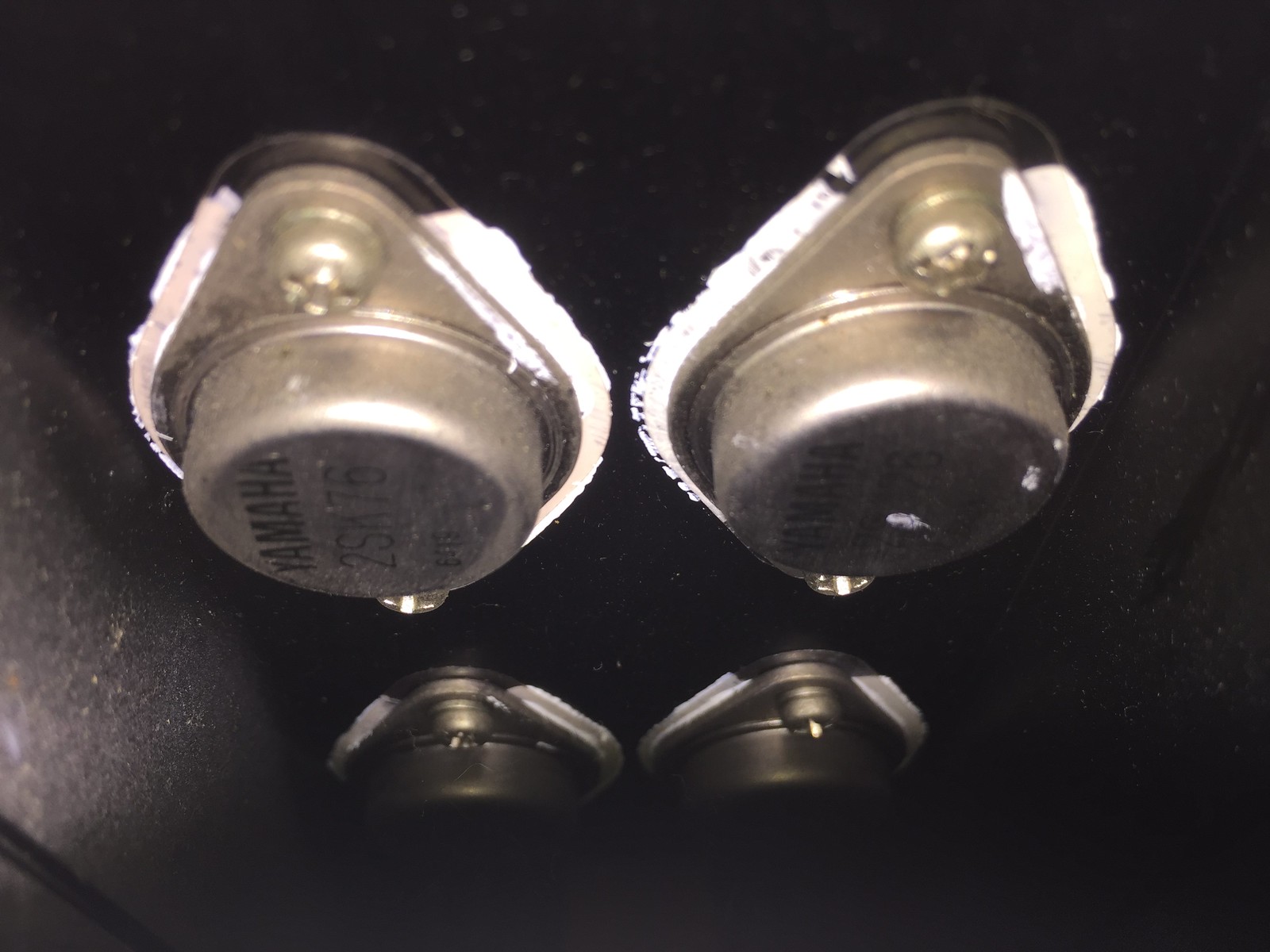
I want to also make sure the V-fets are ok and eventually do a complete restoration. But before i buy all the parts I want to give it a listen and get familiar with the sound and while listening to music go over the service manual and schematics and get familiarized with those as well as the sound ;)

So How do i test the V-fets to see if they are ok? Is it the same method as the Sony V-fets which I have experience with after restoring a Sony TA-4650 with replacement V-fets .

And should I try to turn it on as is and see if I can get it working or would the damaged input board possible cause the death of the V-fets.

Opinions and advice much appreciated .

Here awesome pics ( 1600 x1200) and thanks in advance !!!

36297294296_f964e35263_h.jpg
36173100972_1ef9d81431_b.jpg

36205067041_39012acaba_h.jpg

36341806655_b1414fe859_h.jpg
35944987700_d508f384cf_h.jpg

35505933714_5ed700fe4e_h.jpg
36341806785_e04c6900b5_b.jpg
 
Hello

Defective input board can't dammage your VFET .
I have seen very often on many B2 defective (bad contacts) input board . The only way to repair is to clean the contact inside each switch . You have to be very carefull when doing this . Swiches will not like 2 or 3 opening ...
I think about rebuilt another PCB with other new switches but not really simple to realize (scale problems)
 
B2 original Speaker switches

B2-switches-01-R.JPG

opened oxyded switch :

B2-switches-02-R.JPG

closer view

B2-switches-03-R.JPG

oxyded contacts :

B2-switches-04-R.JPG

cleaned contacts :


B2-switches-05-R.JPG


switch cleaned , ready for use :

B2-switches-06-R.JPG
 
I have a junk B-2 from Japan coming over which will be parted out for a B-2 mega-project that I am doing for friend/customer.
I will discuss with him if he is ok to sell off the input card assembly, if you are interested. No promises until he agrees with it though.
I would say that your mint B-2 deserves it :)

Re testing VFETs: yes it is same method as for Sony VFETs.

The B-2 series have been build with various VFET mounting options, including one series with novelty coating of the heatsink's surface under the VFETs, eliminating the need for washers.
That coating is blue, and your heatsinks are not like that.

Other series had so-called SIL-pads: those do crack when aging, giving potential shorts and VFET failures.
Those should always be preventively replaced.

3rd option like yours.... it looks from the pictures that you have mica washers with white thermal paste under your VFETs.
When leaving untouched, the mica will stay fine. However, if you remove the VFETs, they ought to be replaced.

Could you post a detail photo of your VFETs ?
 
do not plug it in.

Fix the board problem first.
Do a visual inspection of the main cans...but I would replace them first, before plunging in the unit.

One often mistake I see, when older units end up listed for sale and the owner wants to see if it works before listing it. If the filter cans were already "shaky", they would not be able to withstand the inrush current when plugged in after many years. ther is a good chance good chances to take out the v-fets doring this power-up process after long periods on stand-by. B-2 cans are notorious for that.

Open the top and bottom covers. Look for signs of "spillage"

To remove the vfets, it can be done from the top. First you need to see if you have any "juice" left in the cans. test for DC across the red/white wires at the top on both sides (five wire connected to each v-fet bank)
If no "juice" left in the cans, then you are good to snip those wires. Do not bother desoldering them. you can clean up the posts later and redo the wire ends.
you can leave the driver boards in or remove as assembly (with the heat sinks) but you will have to manage another 4 wires per board (+/- 85v and the signal wires)

to remove the heat-sinks...just two screws on top.

When you test the v-fets, it goes without saying...do not mix them. Unlike Sony, Yamaha did not mark the grades. You will most likely find markings on the back..hand writing that is.

good luck!
 
indeed, the VFETs are closely matched per channel; keep VFETs together per channel in case you take them out one day !
 
to remove the heat-sinks...just two screws on top.
:yikes:

There's a small PCB that interconnects the V-FET modules to the driver boards. It breaks real easy if you pull too hard from the top because of the large pin Molex connectors at each end. Better to start by removing the bottom cover and carefully remove those boards after you discharge the main caps. :thumbsup:
 
Last edited:
In my experience, I'd just bypass that input board. I experienced a noticeable improvement in sound quality when I did mine. When the unit was new, you probably wouldn't have, but all these switches and contacts get dirty as the years go by.
 
Hello

Defective input board can't dammage your VFET .
I have seen very often on many B2 defective (bad contacts) input board . The only way to repair is to clean the contact inside each switch . You have to be very carefull when doing this . Swiches will not like 2 or 3 opening ...
I think about rebuilt another PCB with other new switches but not really simple to realize (scale problems)


Yes I have cleaned this type of slider switch before. But one has lost its spring i believe . Will have to check it out once I remove the board.


I may still look at a new board design and build. Maybe add some sort of " direct to driver board" jumper option on the new board to avoid the switch , but I will have to look at everything to see if its even feasible .

I have a junk B-2 from Japan coming over which will be parted out for a B-2 mega-project that I am doing for friend/customer.
I will discuss with him if he is ok to sell off the input card assembly, if you are interested. No promises until he agrees with it though.
I would say that your mint B-2 deserves it :)

Re testing VFETs: yes it is same method as for Sony VFETs.

The B-2 series have been build with various VFET mounting options, including one series with novelty coating of the heatsink's surface under the VFETs, eliminating the need for washers.
That coating is blue, and your heatsinks are not like that.

Other series had so-called SIL-pads: those do crack when aging, giving potential shorts and VFET failures.
Those should always be preventively replaced.

3rd option like yours.... it looks from the pictures that you have mica washers with white thermal paste under your VFETs.
When leaving untouched, the mica will stay fine. However, if you remove the VFETs, they ought to be replaced.

Could you post a detail photo of your VFETs ?

Ill take you up on the board offer if your friends will let it go , Thanks !!!

Yes i noticed I have the Mica vision. On my Sony TA-4650 V-Fet I used Kapton pads with good results so far. I may use those again here. No thermal past needed . I hate that crap ;)

I'll try to get pics of the V-fets for this thread.


do not plug it in.

Fix the board problem first.
Do a visual inspection of the main cans...but I would replace them first, before plunging in the unit.

One often mistake I see, when older units end up listed for sale and the owner wants to see if it works before listing it. If the filter cans were already "shaky", they would not be able to withstand the inrush current when plugged in after many years. ther is a good chance good chances to take out the v-fets doring this power-up process after long periods on stand-by. B-2 cans are notorious for that.

Open the top and bottom covers. Look for signs of "spillage"

To remove the vfets, it can be done from the top. First you need to see if you have any "juice" left in the cans. test for DC across the red/white wires at the top on both sides (five wire connected to each v-fet bank)
If no "juice" left in the cans, then you are good to snip those wires. Do not bother desoldering them. you can clean up the posts later and redo the wire ends.
you can leave the driver boards in or remove as assembly (with the heat sinks) but you will have to manage another 4 wires per board (+/- 85v and the signal wires)

to remove the heat-sinks...just two screws on top.

When you test the v-fets, it goes without saying...do not mix them. Unlike Sony, Yamaha did not mark the grades. You will most likely find markings on the back..hand writing that is.

good luck!

I agree with fixing the board issue first.

I will test the cans and look for any leaking caps. Its what I usually do on a rebuild. had a few in one of the 3 A-1's I restored .

And I'll make sure I label the V-fet locations . I have some foam I can stick them in with some labels .

Now the only thing I need is time !!! ;)

Athanasios
 
Last edited:
:yikes:

There's a small PCB that interconnects the V-FET modules to the driver boards. It breaks real easy if you pull too hard from the top because of the large pin Molex connectors at each end. Better to start by removing the bottom cover and carefully remove those boards after you discharge the main caps. :thumbsup:

yeah, not hard to do from the top. I prefer to remove as an assembly...driver board included..so just the two screws, well 2 + 2 + 1(the ground)
the rest can be disassembled later and I haven't broken any bridge boards yet :biggrin:

B2_flock2.PNG


or the other way...leave the driver board in, then you have to have the bottom cover off as well and work the "bridge" board..


In my experience, I'd just bypass that input board. I experienced a noticeable improvement in sound quality when I did mine. When the unit was new, you probably wouldn't have, but all these switches and contacts get dirty as the years go by.

yes they do and so does everything else after 40 years. They are not that hard to clean tho.

Imagine if you had to worry by-passing switches on one of these:
C-1.PNG

or worse, having to clean them :-(
 
Don't forget to precisely adjust the front panel as necessary once all switches have been cleaned, the front panel (if misplaced) can hold one switch and stop it from moving freely. It is a critical adjustment but necessary to do if you want to recover normal function of all the switches !
 
Last edited:
I am an incorrigible yamahahoarder and I blame everyone on this site for my addiction (particularly those that suggested I should listen to a v-fet amp the first time) :biggrin:
 
Last edited:
Don't forget to precisely adjust the front panel as necessary once all switches have been cleaned, the front panel (if misplaced) can hold one switch and stop it from moving freely. It is a critical adjustment but necessary to do if you want to recover normal function of all the switches !
PITA to do on the C-1.
 
Hello Nashou

They are old type VFET . Silicon grease look "replaced" some years ago . Did you make any measurement ? A curve tracer will do the job very well . Ohm meter is not enough in my point of view except for short circuit !
 
Here is some curves from a defect V-FET non detectable with ohm-meter

B2-2SJ26-6205-HS-JFET-Id_Vds.JPG

another one

B2-2SJ26-6205-HS-JFET-Id_Vgs.JPG

curves from a good one

B2-2SJ26-6221-HS-JFET-Id_Vds.JPG

:thumbsup::thumbsup:
 
I do have a curve tracer the Leader LTC 905 that I have never used. It connects to an oscilloscope . I'd just have to figure out how to connect it to the scope and the DUT , along with what voltage settings etc.

I attached the manual for anyone interested . An maybe some advice could be given ;)
 

Attachments

  • Leader-3783.pdf
    882.1 KB · Views: 20
Last edited:
I do have a cure tracer the Leader LTC 905 that I have never used. It connects to an oscilloscope . I'd just have to figure out how to connect it to the scope and the DUT , along with what voltage settings etc.

I attached the manual for anyone interested . An maybe some advice could be given ;)
100mA might not be sufficient to test the power V-fets
 
B2 original Speaker switches
Very nice work Cinic! Thanks for posting the pictures. Both of my B-2's are misbehaving right now because of those nasty switches; it's very annoying and because I've only ever had one source connected to it/them and I've never change the attenuator settings since I've owned them I'm thinking I'm going to add some jumpers to that board soon to remedy the problem. They can always be remove later if new switches become available. :thumbsup:
 
Back
Top Bottom