Zilch's AK Design Collaborative - Econowave Speaker

Gentlemen!

Here are my pictures. Please count me as an Ewaver! :D:D:D

My R1 and R2 are 5 watters. :stupid: The only resistors that were handy at the time. I am running with eico 14s. They are 14 watts each. And the resistors are cool. But don't worry. I've already ordered replacement resistors. Trust me. They will be beefed up. Way UP!

Hey Andy. Would my enclosures be light enuf to make it darker or more like red? Please help. Other than that, they sound beautiful. Beautiful! I was about to sell my cartridge thinking that it sounded dull. It wasn't my cartridge. Nope!

Skywave. I am gonna try to post some graphs later. My internet is down. I am piggy backing on our neighbor's wifi.
Thanks guys. Really!

Excellent! The fever is spreading. Nice sounding huh? Really dig those mini baffles! Ewave on brother.:thmbsp:

Russellc
 
Another Econo-wave added to the portfolio....

Apologies for interrupting the technical aspects of the thread.....

I finally got my waveguides today and installed them quickly into the existing system which now incudes:

- The Selenium D220Ti/JBL waveguide
- JBL 4647A bottom cabinets w/JBL 2226H woofs
- Bi-amped w/Behringer CX4300 xover at about 2kHz w/0.3ms delay on the horns and the CD equalization switched in.
- McIntosh MC-225 tube amp driving the Econowaves
- Hafler DH-200 driving the woofer cabinets

As you can see from the pictures, the original JBL 2380 horn with 2445J large format drivers sitting on the floor are quite a bit bigger and heavier. Plans are to sell some other gear and then recone a set of old 2225 woofers into 2235Hs and add another set of Zilch-plugs into the vents.

I'll let the horns burn in a bit this way while I dink around with the crossover and try to set up my rather simplistic measurement system. That includes an AKG C1000 mic, a Presonus FireStudio audio strip into a laptop running RoomEQWizard, a freeware package to get some of the parameters better matched.

And the fun begins.....

Cheers,

David
 

Attachments

  • Econowave and xover.jpg
    Econowave and xover.jpg
    55.2 KB · Views: 164
  • JBL Econowave.jpg
    JBL Econowave.jpg
    44.2 KB · Views: 426
Apologies for interrupting the technical aspects of the thread.....

I finally got my waveguides today and installed them quickly into the existing system which now incudes:

- The Selenium D220Ti/JBL waveguide
- JBL 4647A bottom cabinets w/JBL 2226H woofs
- Bi-amped w/Behringer CX4300 xover at about 2kHz w/0.3ms delay on the horns and the CD equalization switched in.
- McIntosh MC-225 tube amp driving the Econowaves
- Hafler DH-200 driving the woofer cabinets

As you can see from the pictures, the original JBL 2380 horn with 2445J large format drivers sitting on the floor are quite a bit bigger and heavier. Plans are to sell some other gear and then recone a set of old 2225 woofers into 2235Hs and add another set of Zilch-plugs into the vents.

I'll let the horns burn in a bit this way while I dink around with the crossover and try to set up my rather simplistic measurement system. That includes an AKG C1000 mic, a Presonus FireStudio audio strip into a laptop running RoomEQWizard, a freeware package to get some of the parameters better matched.

And the fun begins.....

Cheers,

David

Holy crap! it looks just like my livingroom! With the 2225H, I had much better sound with all ports open. With the recones to 2235H, (WOWIE!)
I am deciding between one port and two closed, albeit with make shift rolled up microfiber towel standing in for second Zilch plug. Try it playing some nice music that really pressurizes the room, and pull the plug on the 2226H, I think youll see what I mean. Its all a matter of personal taste of course, but I though it was a little dead compared to all four open. With 2235H, the mids are a little muddied with only one on SOME recordings.

Have fun, I'm watching as I have the exact same setup, and its kickass for sure!
 

Attachments

  • IMG_1902.jpg
    IMG_1902.jpg
    50.5 KB · Views: 192
Nice sounding huh?
DEFINITELY!
Post a close-up of that there X-over when you're back online, please.
I posted a picture a while back. I will try it again. How do you guys post such big pictures? I tried. But it says my file is too large.
Are you sure waveguide won't fit
May be I can. But there is heavy bracing behind the baffle. I will have to do some major work to fit it in.

I will definitely flip the speaker. I am sort of OCD. I can't put a smaller circle (port) below a bigger circle (woof). You know what I mean? That was the reason why I put the speakers as they are. But, I will flip it over.

Thanks guys.
 
Any picture of the finished product?
There is no single product. It's a DIY design concept.

So far, several dozen versions by different builders have been shown in this thread.

Sorry, but for now, you're going to have to page through to see them.... :yes:
 
Apologies for interrupting the technical aspects of the thread....
No problem.

We're just in full technoblather mode while waiting for others like yourself who are actually DOING stuff to post their projects here.... ;)

And the fun begins.....
Heh, heh. :guitar:

Your system is certainly looking familiar to E'Wavers. From what Wayne's telling us, it's a low-budget 4-Pi equivalent.

I'll be interested to see what your measurements show. If the generic compensation in CX3400 is too "hot," which several of us have found it to be, just build the E'Wave crossovers. High sensitivity version for 2225/6, low for 2235H, according to Russell's findings. :yes:

I'll take a pair of the Four Pi. Nice!
You've got almost all of the requisite pieces.... :thmbsp:
 
Oh, I see, very good. I thought those might be from my chart, but wasn't sure if you actually built my networks or simulated them or what.
It's CLIO MLS measurements of the actual filter performance, all eight variants on your chart. Has anyone other than the Zilchster ever done this? Are my results comparable?

attachment.php


I would not use the 6dB or 8dB versions, for the reasons I've stated earlier. There isn't enough padding to remove for top-octave augmentation. There is only half the needed slope. I added the 6dB and 8dB component values to the chart only to show what would be required, for completion's sake.
Perhaps not in your product(s), or not with the driver/waveguide combinations you use, but I've just demonstrated that with a bit of tweaking, they work with E'Wave.
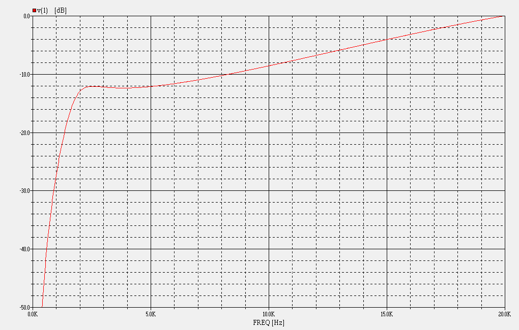
How is that? The curve begins (or ends, according to one's particular perspective) at 0 dB at some very high frequency, depending upon the value of bypass capacitor used, which establishes one point of the curve. To produce more attenuation and maintain the proper slope, a progressively smaller value cap is required. Conversely, lesser attenuations may be accomplished with higher values to generate the correct compensation.

At some point, of course, we run out of gas, and it's clear from measurements using the actual E'Wave components and independent empirical determinations by E'Wave experimenters, Jack has pushed this envelope to the max in our high-sensitivity filter. I've approached that with the mods to your 6 dB and 8 dB values I show above. Using a 0.47 uF bypass capacitor, the filter doesn't have the requisite headroom to provide full compensation at these lower attenuations, which is why both Jack and I used higher values, 0.68 uF, 1.0 uF, and ultimately, 1.5 uF. As you suggest, the slope is too shallow, otherwise.

Geddes tells us that all compression drivers are created equal, but then proceeds to outline why he chooses to use a particular one over all others. From a theoretical perspective, it's convenient (and useful) to define and consider these concepts in generic terms. However, when the "rubber hits the road," detail matters, and in detail, every combination is different; there's an optimum, typically different, solution for each of them.... :yes:
 

Attachments

  • Verifying Wayne's Chart.jpg
    Verifying Wayne's Chart.jpg
    67.6 KB · Views: 778
Reticulated Foam

After doing a bunch of internet searches and searching local stores like, hobby lobby, petco, ace hardware, I found some online suppliers that appear to be the best price.

http://www.thefoamfactory.com/opencellfoam/filter.html

Yes this stuff is 30 ppi.

http://www.thefoamfactory.com/tech/FilterTech.html

This company price matches 110%

Bonus, the company below sells it for less.

http://www.foamandfoam.com/out_door_foam.htm

Hope this helps everyone out there.

I am trying to decide how to construct the best "phase plug".

I am likely to buy some 1/2 and make a pyramid shape.
 
Here are a couple pic's of the plugs that I make, they are 1.5" wide at the base, and 1" tall.
(I just use a good pair of scissors to shape them, takes a bit of practice)

The sides go up roughly 1/2" before making the rounded taper so it fills the center of the guide.
(They squish down a bit to fit in the guide and hold themselves in place)

They only drop output from the driver about 1db as far as I can tell and do work rather well to. :music:

Geddes says to fill the whole horn, but the experimenting I've done says this little plug works great.
 

Attachments

  • plug.jpg
    plug.jpg
    105.1 KB · Views: 53
  • plug_hnd.jpg
    plug_hnd.jpg
    150.6 KB · Views: 63
i wouldn't actually recommend compressing the foam if you can help it. A bit of spray adhesive would hold it in place well.
 
Perhaps not in your product(s), or not with the driver/waveguide combinations you use, but I've just demonstrated that with a bit of tweaking, they work with E'Wave.

I think your solution works quite well with the Selenium compression driver you're using.

This isn't so much an issue with the horn as it is the driver. Constant directivity horns and waveguides don't alter the response of the driver. There is no collapsing directivity to increase on-axis SPL at high frequencies.

To provide equalization for constant directivity, one must provide the conjugate of the driver's power response. A purely pistonic diaphragm will basically fall at 6dB/octave through its passband, and so the slope of CD equalization is 6dB/octave augmentation. The power response falls at 6dB/octave rate above some frequency, set by the mass of the diaphragm. That's where the crossover's 6dB/octave augmentation begins.

There are three sources of rolloff in a compression driver. The first is mass rolloff, starting a gentle 6dB/octave downward slope through much of the driver's passband. It's what CD equalization is for. The second is voice coil inductance, which introduces a second pole around 16kHz-18kHz or so, increasing rolloff slope to 12dB/octave. This marks the end of the driver's passband. The third is the low-pass filter formed by the front chamber, the space between the diaphragm and phase plug. This and the dimensions of the phase plug slots and throat aperature bring the total slope to about 18dB/octave rolloff.

This is a description of a compression driver with a diaphragm moving as a rigid piston. It doesn't include any resonance of the diaphragm membrane. In fact, ripples appear across its surface at high frequency, and this can be seen as a jagged upper end. These breakup modes increase output at high frequency, in a series of peaks and dips. Some drivers have well damped breakup modes that you can hardly detect. Others have more pronounced modes.

The driver you've shown has a pretty healthy peak at 12kHz or so. I've seen this in other drivers too. It's not uncommon in compression drivers with titanium diaphragms. Some sound pretty good, with ample "sparkle". Some are too harsh. You can definitely hear the difference between a driver like this and one with a diaphragm that's more damped and smoother.

attachment.php

Top-octave compensation can mean many things to many people, I suppose. It is always the conjugate of driver power response. One thing in common with all compression drivers is the 6dB/octave mass rolloff curve. In addition to this, it can include notch filters for breakup modes or additional augmentation for a sagging top end via a peaking coil. I've seen both approaches, and others.

Your solution has been to modify the basic shape of the 6dB/octave curve to account for the peak from diaphragm breakup. Not a bad approach, in my opinion.

The R1/R2/C1 values I've chosen provide a pretty straightforward 6dB/octave augmentation starting around 5kHz, with flat response prior to that. However, there's a requirement that there be 12dB attenuation to begin with. It doesn't provide as much augmentation for versions having less padding, it can't. But that's not important to me because there are no direct radiating woofers efficient enough to match a compression horn with less than 10dB padding. The horn gains about 10dB.

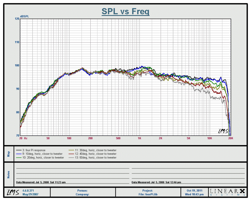
In the end, the response curve of a completed loudspeaker looks like this:

fourPi_horizontal_left.gif

Geddes tells us that all compression drivers are created equal, but then proceeds to outline why he chooses to use a particular one over all others. From a theoretical perspective, it's convenient (and useful) to define and consider these concepts in generic terms. However, when the "rubber hits the road," detail matters, and in detail, every combination is different; there's an optimum, typically different, solution for each of them.... :yes:

I agree. This is one of the areas where I do not agree with Geddes. I understand his philosphy, that compression drivers are a commodity item at a certain level. I think that is probably what he really means, that above a certain quality standard, all drivers are equal. But certainly not all drivers are the same.

I think it is a simplifying assumption. They're all equal if they're equal, but not if not. If the diaphragms were all the same, I'd probably agree, but they're not. Some have smooth rolloff. Some have a breakup mode peak in the top octave. That's the biggest difference between them, in my opinion.

Take the driver you've chosen, for example. It falls at the expected rate from 5kHz to 10kHz, about 6dB in that octave. But then it jumps about 4dB before beginning to fall again. This is a breakup mode, and it gives the driver much more output in the top octave than a pistonic diaphragm would have. How do you deal with that?

In your case, your answer was to manipulate the augmentation curve. That's reasonable, and makes the average output more even overall. Your driver basically only falls about 8dB through two octaves because of the diaphragm breakup peak. So you modify the top-octave compensation to accomodate that. You're basically looking for 8dB augmentation, not 12dB.

Then again, if you were to narrow your driver choices to only those with well damped breakup, then you would probably be closer to what Geddes is talking about. When the diaphragm is pistonic or reasonably well damped, it behaves very predictably, with output falling uniformly at 6dB/octave above mass rolloff, for a total of 12dB spanning two octaves. The choice of drivers becomes almost a commodity and equalization curve standardizes to this:

Top_Octave_Compensation.gif
 
Does Geddes say that all compression drivers are created equal or that they are a commodity and don't need to be expensive to be good? I think his position is that they don't need to expensive and any reasonably decent compression driver can be made to sound good with proper implementation.
 
i wouldn't actually recommend compressing the foam if you can help it. A bit of spray adhesive would hold it in place well.


That's what I woulda thought to Dave, but if there not that wide an squish just
a bit they leak around the edge, do not work as well even measuring, so squish a
bit does work rather well here and no adhesive needed.:thmbsp:


By being just a bit wider then the opening they conform themselves the horns shape.
 
I am likely to buy some 1/2 and make a pyramid shape.
According to Geddes, the entire waveguide must be filled, not just the throat, and thin pieces cannot be stacked or glued to accomplish that. It must be hewn from a single homogenous piece. His are domed, in addition, apparently, as well.... :dunno:

80076/2295=34.8915​
 
I posted a picture a while back. I will try it again. How do you guys post such big pictures? I tried. But it says my file is too large.
Take the pictures at a lower resolution, or resize them to 640 x 480 in your image software before posting.

May be I can. But there is heavy bracing behind the baffle. I will have to do some major work to fit it in.
Look at how much smaller the rapid flare of the waveguide becomes behind the baffle; way less clearance is required after merely the baffle thickness.... :yes:
 
According to Geddes, the entire waveguide must be filled, not just the throat, and thin pieces cannot be stacked or glued to accomplish that. It must be hewn from a single homogenous piece. His are domed, in addition, apparently, as well.... :dunno:

80076/2295=34.8915​


Ideally, you are correct, I suspect that Kegger's version isn't having as much of an effect on the reduction of HOMs as much as probably acting as some sort of high pass filter. However, his concerns from stacking stem from the ability to stack them while retaining the properties of a single piece. You can't glue because it would make the foam act like something other than 30ppi reticulated foam. Some people have used stacked foam plugs with the same audible effect buy using thin string so sew the pieces together and there is some message of using nylon of some sort to attach them.

If you can find a way to keep the foam acting like a single lug, then you are ok.
 
The high pass filter certainly "could" be 1 aspect.

My hypothisys is turbulance in the horn throat an exit area of the horn throat, as I see that
could be a hostile enviornment coupled with the fact how it holds together better at high SPL.
 
Back
Top Bottom