Project Amp

Get the part number out of the service manual and try
http://www.partstore.com/default.aspx?s=google&sw=nonspecifc
If it looks like a normal size fuse you can try replacing it with a fast blow 10A. That should be ok, it will probably blow before the thermal one would. If it looks unusual, order the Sony part.

*snip*

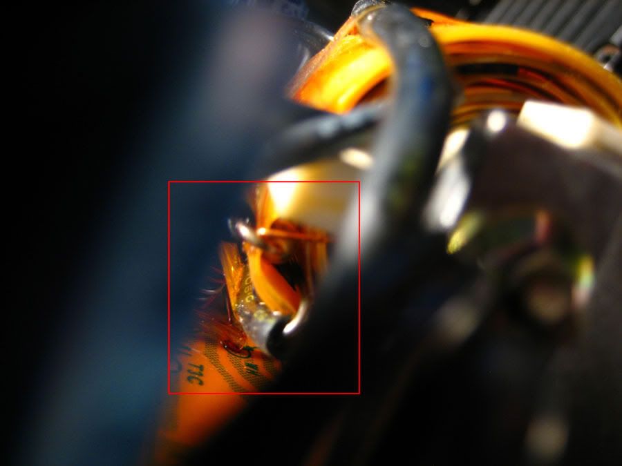
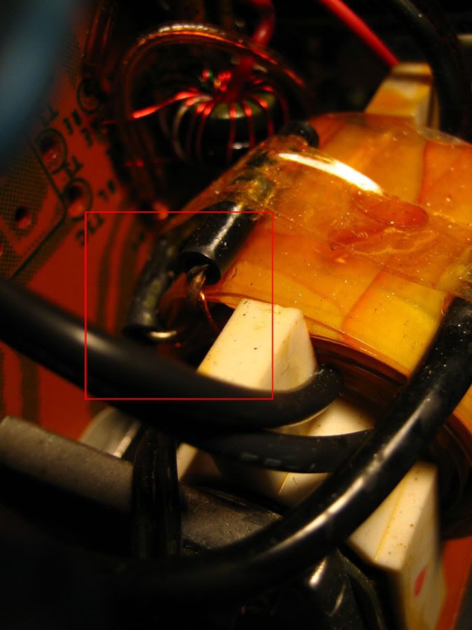
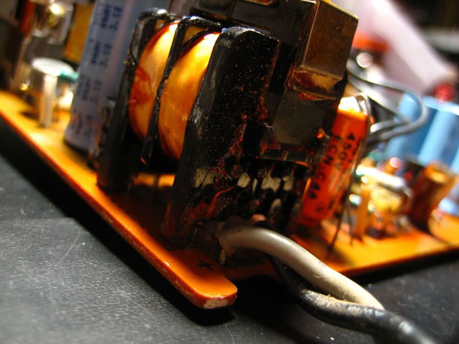
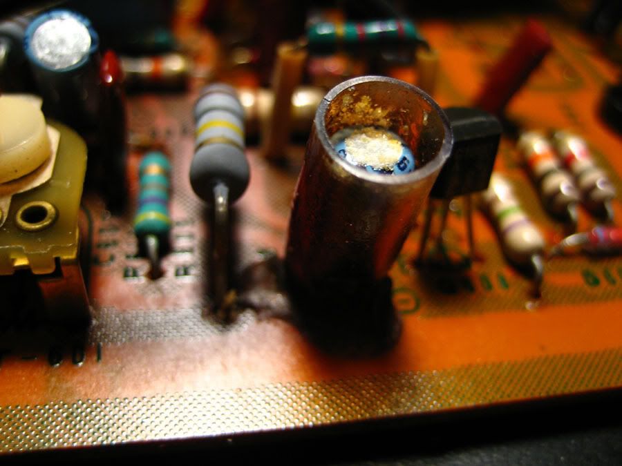
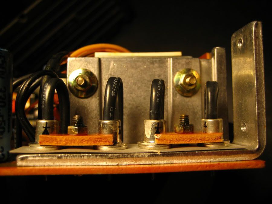
The thermal fuse appears to be akin to a resistor, and not a typical glass fuse. The markings from the service manual state "THERMAL FUSE - 10A 109°C."

I'll try searching for the Sony p/n.

Thanks, Doc.


Philip.


Thermal Fuse, Sony
P/N 1-532-496-00
$12.53

Ouch.
 
Last edited:
I found a cracked resistor next to the hottest capacitor. I've never seen that before.

Also attached a photo of the thermal fuse.
 

Attachments

  • hot!.jpg
    hot!.jpg
    148.2 KB · Views: 60
  • thermal_fuse.jpg
    thermal_fuse.jpg
    97 KB · Views: 57
It doesn't look like it overheated. It might be just a crack in the coating, but you should replace it anyway.
 
If you can't find the Sony part, use Digikey part# 283-2083-ND.

That looks like it would work nicely-- can't figure out why I couldn't find it before, though. I have to order a few things from Digikey... I really should make a list...

Thanks Warren.
 
Alright, I pulled the PLPS today and took a gander. Immediately I've found a corroded capacitor and what looks like burnt flux all over the input choke. There's a transformer in the back that looks like it has a fuse buried within its windings which tests out okay (thank goodness) so I think it's safe to assume that the tranny's okay. I noticed some monster diodes that look like female RCA plugs and also that all the wires are spec'd at 105°C while the caps are all 85°C-- those will all get replaced.

I'm really really glad that I didn't just replace the thermal fuse and turn it on. Lots to test. I'm going to go over this whole amp with my iron (eventually).
 
Sounds like the switching transistors may be ok then. I would replace the fuse and see what happens. You need to see where you are as a starting point, if for no other reason than so that if it is working now, but is broken after you replace the caps, you will know you did something wrong. If you just replace the caps and fire it up, you won't know if you killed it, or it didn't work to begin with. It's very possible the fuse blew because of the current surge at turn on, or the previous owner momentarily shorted the speaker wires. It's also possible there is a problem in the power amp, but you won't know unless you check it out before you start replacing parts.
 
Sounds like the switching transistors may be ok then. I would replace the fuse and see what happens. You need to see where you are as a starting point, if for no other reason than so that if it is working now, but is broken after you replace the caps, you will know you did something wrong. If you just replace the caps and fire it up, you won't know if you killed it, or it didn't work to begin with. It's very possible the fuse blew because of the current surge at turn on, or the previous owner momentarily shorted the speaker wires. It's also possible there is a problem in the power amp, but you won't know unless you check it out before you start replacing parts.

At this point I'm thinking of giving the solder side an alcohol bath, replacing that one corroded cap, and putting on some new thermal grease.
 
I replaced the fuse with the same type (my downtown electronics store stocked the exact part for $1/ea.), the corroded cap on the PLP, and closed everything up.

I set the switch of 'ON' and plugged it into a turned-off power bar, stood back, and turned on the powerbar.

My desk lamp dimmed for a second but the meters didn't light up on the amp, so I quickly turned off the bar. Should I have let it 'warm up?'


Upwards an onwards.


P.S. Does it matter that there are no jumpers between the PRE / POWER plugs?


P.P.S. Standing further back and waiting a few seconds more and I hear a relay kick on.
 
Last edited:
You need the jumpers installed to pass signal from the preamp section to the amp section.
 
Alright, it works!!

Test through my headphones with MP3 player as the source. Used custom cables as a jump, but I might get some large gauge copper and make some jumpers.

Lots of scratchiness... mute doesn't actually Mute for some reason. I still want to replace some parts before it becomes my daily driver.


I owe you a beer, Warren.
 
Cool! Now you can go ahead and recap it with 105C caps. Wait till you hear how sweet this baby sounds. I repaired a stand alone amp from this series and I really liked the sound. Check the manual and see if the relay is shown there. The amp I worked on had the relay, and the supply section looks to be the same one. Someone may have bypassed it. As I recall, the relay is for a soft start. Those ceramic resistors near where the relay goes are in series with the supply and the relay shorts them out after a short delay.
 
Do mylar and ceramic caps last longer than electrolytic caps? I also probably have to replace out of spec resistors, clean some crap (birdseed?) out, whole nine yards.

Might as well wash the bare chassis while I'm at it. I refurbished a pair of speakers while waiting for the amp and will to post the documentation-- might do the same thing with this amp.


Philip.
 
In the supply, use 105C electrolytic caps only. In the audio signal path you can replace electrolytics with Mylar or polyester. Polyester is the same as Mylar, they just don't pay a royalty fee to DuPont. Don't replace an electrolytic with ceramic. Be careful cleaning; if you remove the heatsink grease, replace it. No need to replace resistors, they don't usually go out of spec. They are either open or good.
 
In the supply, use 105C electrolytic caps only. In the audio signal path you can replace electrolytics with Mylar or polyester. Polyester is the same as Mylar, they just don't pay a royalty fee to DuPont. Don't replace an electrolytic with ceramic. Be careful cleaning; if you remove the heatsink grease, replace it. No need to replace resistors, they don't usually go out of spec. They are either open or good.

What I meant was should I replace the ceramic / mylar caps that are already in there?

I've run across old resistors where they're been rated at 5% and have been out by 20%, so I might just test a bunch and see where I stand. On the PLPS board there's some burning of the circuit board around some of the bigger resistors, so for sure I'm checking them.

But thanks for the tip about replacing the electrolytics in the signal path, I've heard this before. I should do a straight replacement value-for-value? I've also heard that polyester are the closest to a perfect capacitor, but a lot more care needs to be taken when installing them, or am I thinking of polypropylene capacitors...


Philip.

P.S. I'm definitely not finding the relay in either the US/CAN schematic nor the AEP/UK/E schematic. Revision?

P.P.S. Even the component layout in the service manual shows it unpopulated... was the PLPS used in other amps? It could be that this relay just was unneeded in this amp...
 
Last edited:
I wouldn't bother replacing ceramic and mylar caps, I don't see them degrading performance that often. They go open or shorted, but I don't see them losing capacitance. I guess the relay isn't needed in this model.
 
I wouldn't bother replacing ceramic and mylar caps, I don't see them degrading performance that often. They go open or shorted, but I don't see them losing capacitance. I guess the relay isn't needed in this model.

I'll triple check 'em all anyways. I don't have an capacitance meter, but OHM meter should do it.
 
Back
Top Bottom