Hi,
I recently received an AU555 in need of some repairs from a member here, and thought it would be worthwhile starting a thread to chronicle the progress in restoring this amp.
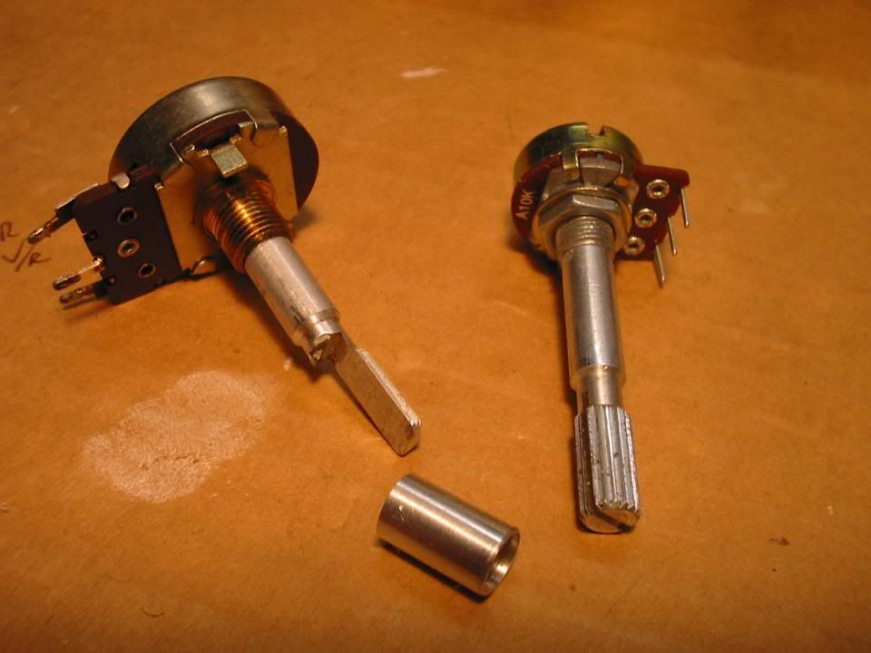
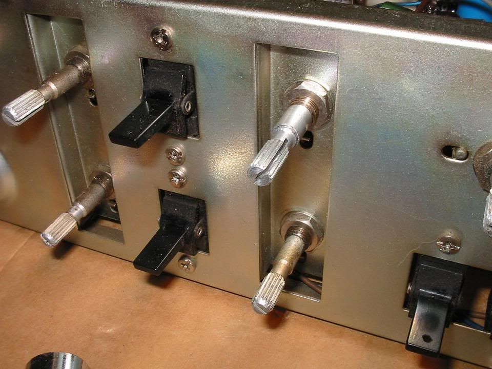
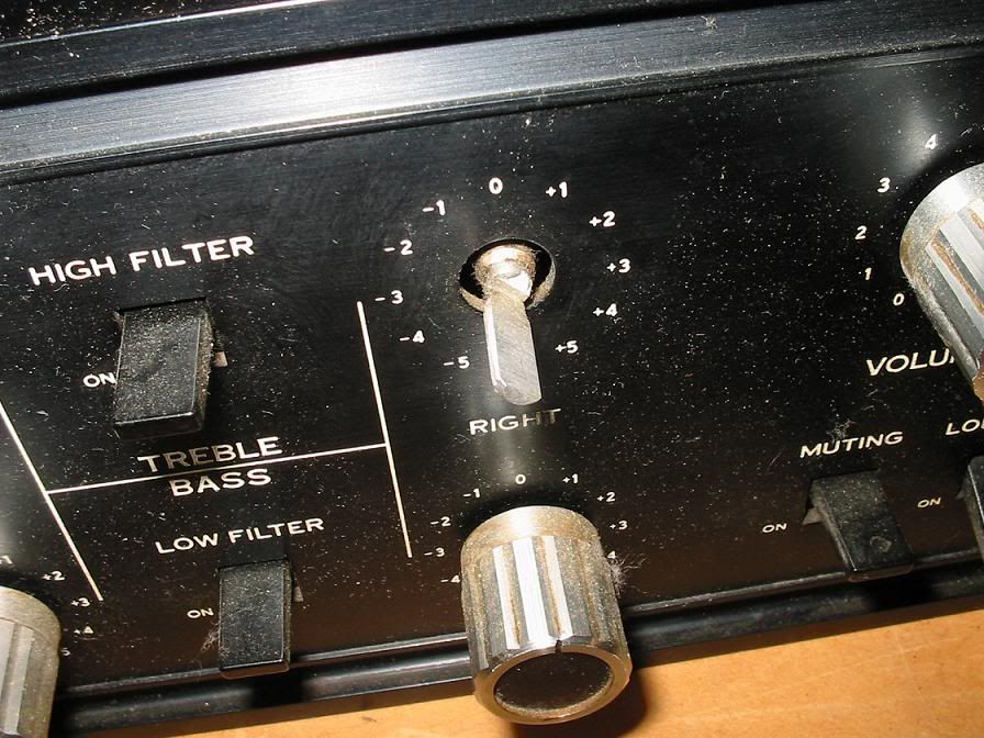
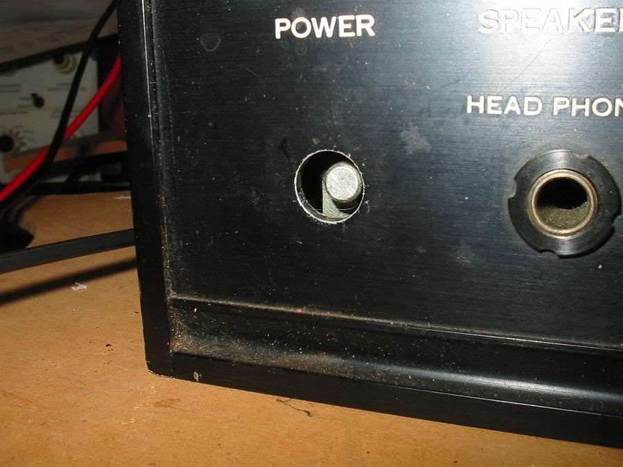
It suffered the dreaded "pop then smoke" syndrome, and had previous issues with crackle on the left channel. Also the right channel treble pot has a busted shaft and the knob is missing, as is the power switch button.
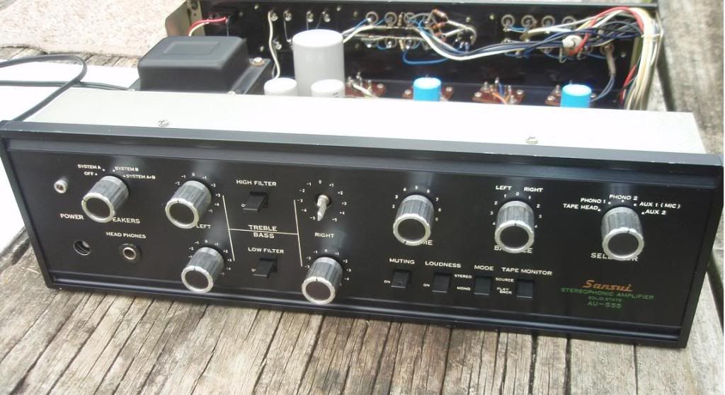
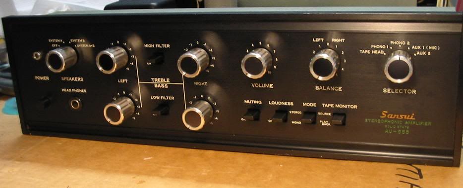
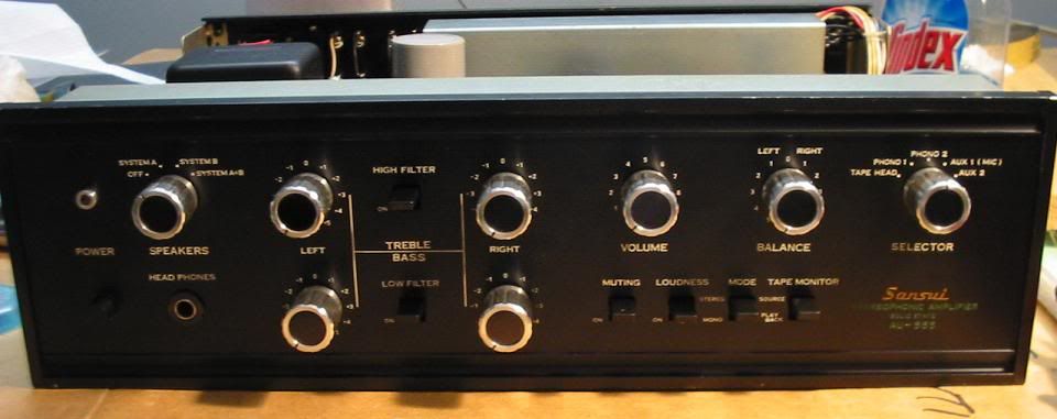
Front panel
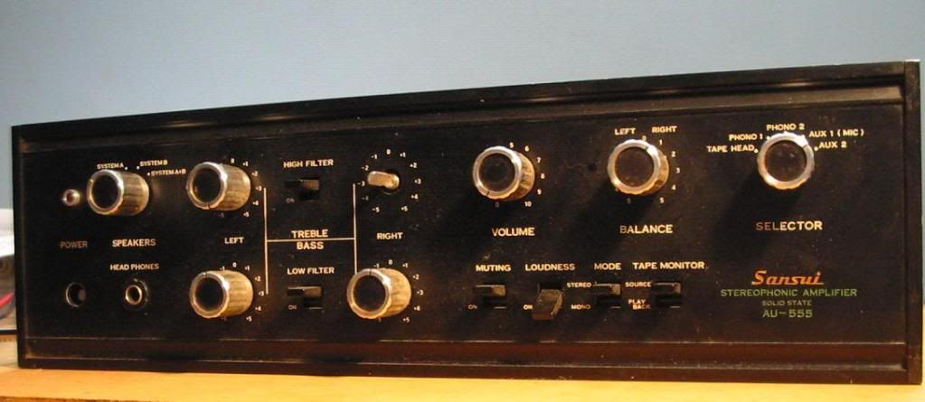
busted pot shaft
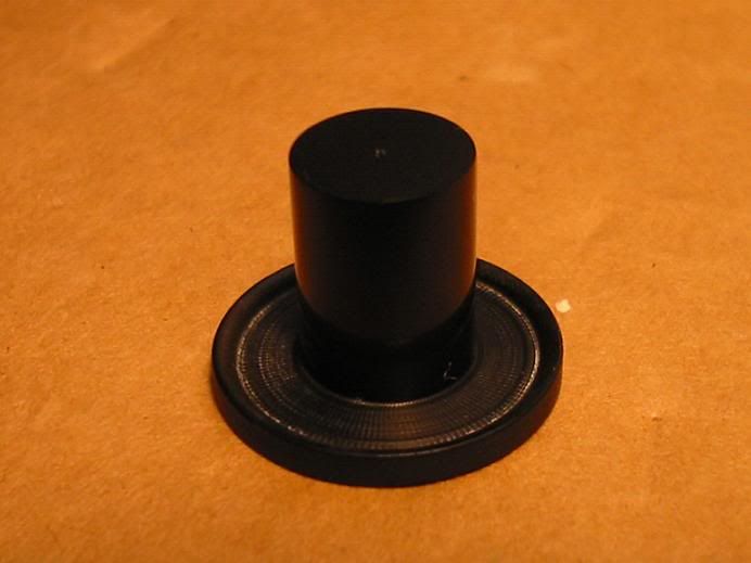
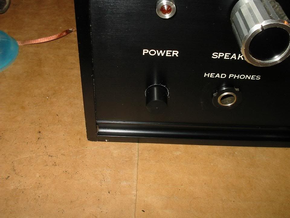
missing power button
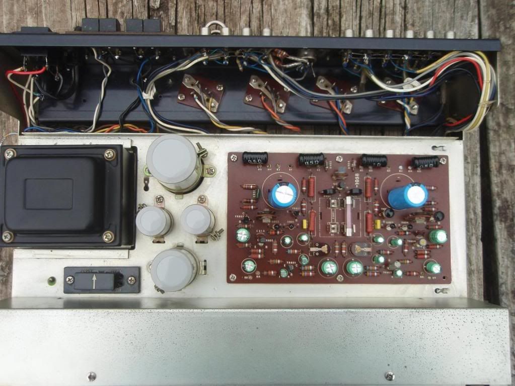
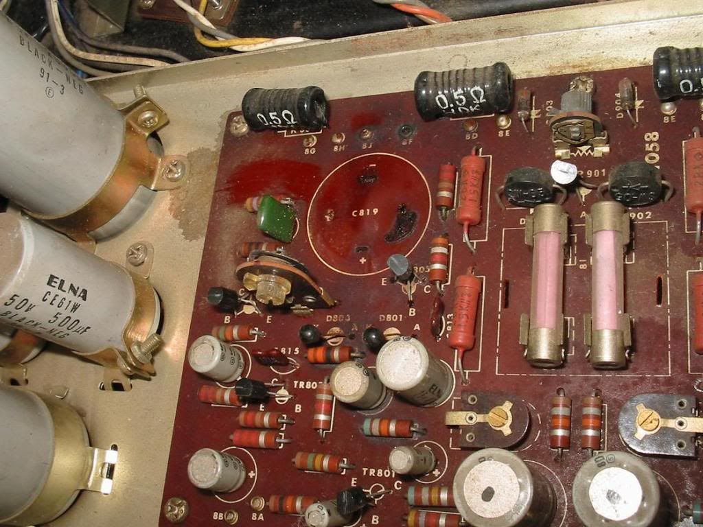
Covers off, and it was evident that the left channel output coupling cap had failed (Both Left and Right channel caps had been replaced sometime in the past).
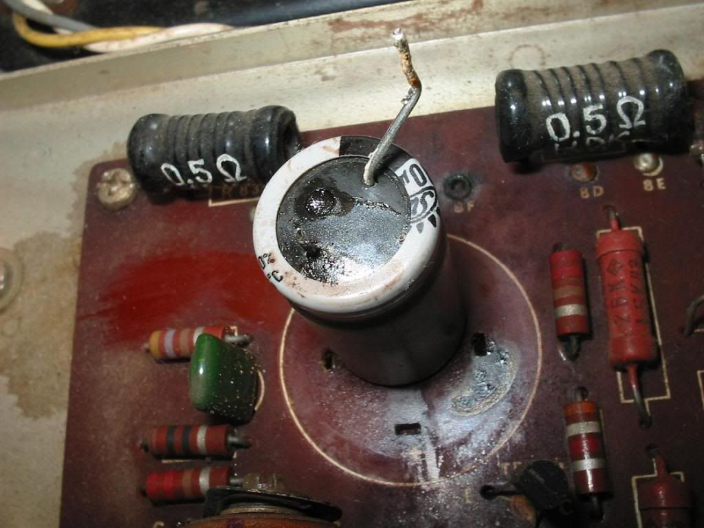
Cap removed
View of Cap base
Decided to start the restoration with a recap of the driver board
Driver Board Recap complete
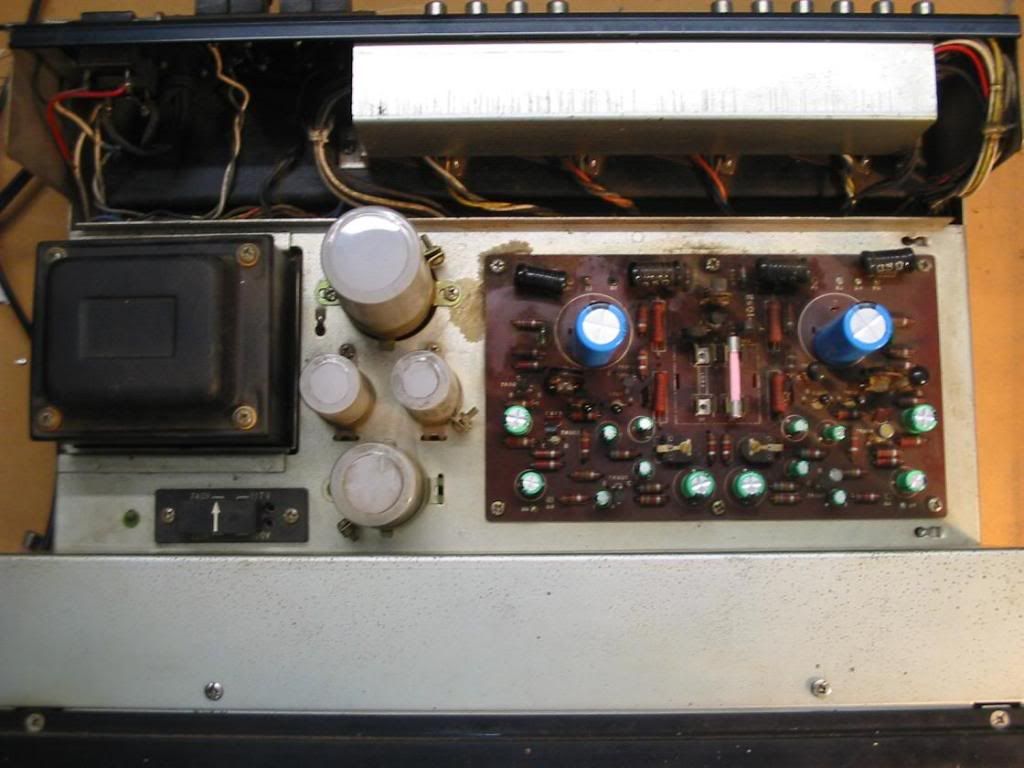
A good look over the unit showed both channels' output transistors (2SD180) have been replaced with 2N3055's, and a lot of the signal transistors in the left channel (preamp, tone and driver) have also been replaced at some time in the past, possibly in an effort to fix the crackle problem.
Powered her up after the recap, and both channels worked, although the dreaded crackle was evident in the left channel, getting slighlty worse as the unit warmed up. Checked and set bias and AC balance, but left channel is a bit flakey and tends to drift/jump around a little (both bias and AC balance). Removed the pre-out/main in jumpers, crackle was unchanged so it appears that it is being generated in the driver circuit.
Tried changing out D801/D803 with 1N4148's but no difference. All NPN's in the left channel had been previously changed out for BC639's as note above, and the PNP for a BC640. Have also "de oxited" the bias and ac balance pots.
Left Channel driver schematic -
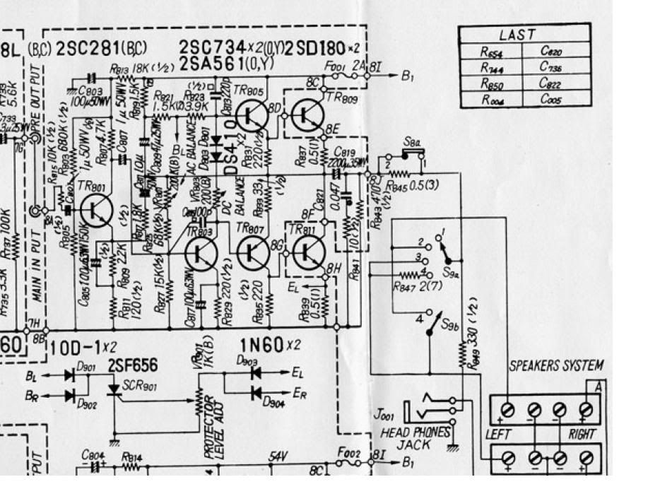
Any suggestions as to the next steps in resolving the crackle issue would be thankfully received. Also would be happy for thoughts/opinions on whether it would be worthwhile changing the output transistors from the 2N3055's to something closer spec wise to the originals, and whether the BC639/BC640 are acceptable alternatives to the original transistors in the driver circuit (2SC281, 2SC734 and 2SA561).
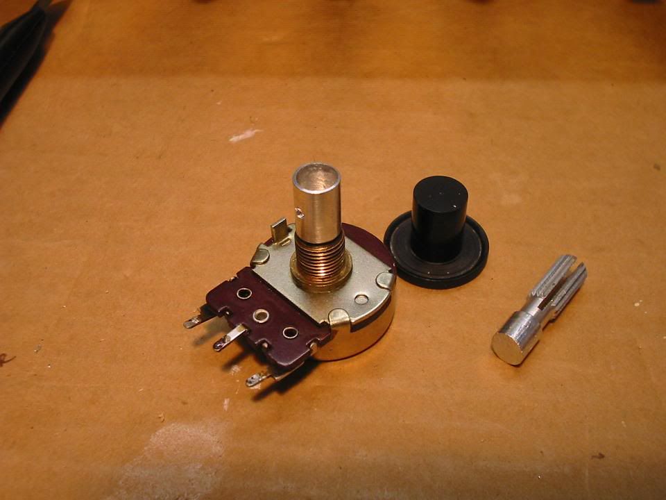
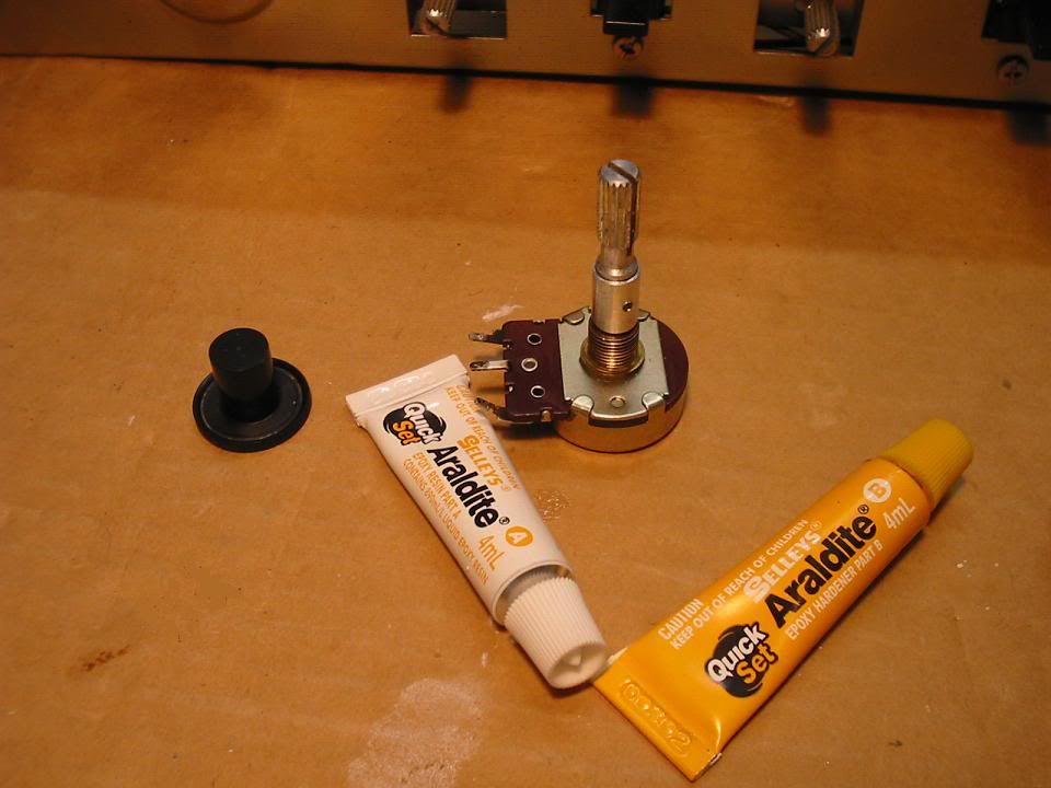
Progress on replacing the damaged Treble Pot will be posted shortly, and procurement of a new knob for treble pot is underway.
If someone with an AU555 could measure the diameter of the power button, and how far it protudes from the front panel that would be greatly appreciated, I am organising the manufacture of a replacement and need these measurements.
Cheers
John
I recently received an AU555 in need of some repairs from a member here, and thought it would be worthwhile starting a thread to chronicle the progress in restoring this amp.
It suffered the dreaded "pop then smoke" syndrome, and had previous issues with crackle on the left channel. Also the right channel treble pot has a busted shaft and the knob is missing, as is the power switch button.
Front panel
busted pot shaft
missing power button
Covers off, and it was evident that the left channel output coupling cap had failed (Both Left and Right channel caps had been replaced sometime in the past).
Cap removed
View of Cap base
Decided to start the restoration with a recap of the driver board
Driver Board Recap complete
A good look over the unit showed both channels' output transistors (2SD180) have been replaced with 2N3055's, and a lot of the signal transistors in the left channel (preamp, tone and driver) have also been replaced at some time in the past, possibly in an effort to fix the crackle problem.
Powered her up after the recap, and both channels worked, although the dreaded crackle was evident in the left channel, getting slighlty worse as the unit warmed up. Checked and set bias and AC balance, but left channel is a bit flakey and tends to drift/jump around a little (both bias and AC balance). Removed the pre-out/main in jumpers, crackle was unchanged so it appears that it is being generated in the driver circuit.
Tried changing out D801/D803 with 1N4148's but no difference. All NPN's in the left channel had been previously changed out for BC639's as note above, and the PNP for a BC640. Have also "de oxited" the bias and ac balance pots.
Left Channel driver schematic -
Any suggestions as to the next steps in resolving the crackle issue would be thankfully received. Also would be happy for thoughts/opinions on whether it would be worthwhile changing the output transistors from the 2N3055's to something closer spec wise to the originals, and whether the BC639/BC640 are acceptable alternatives to the original transistors in the driver circuit (2SC281, 2SC734 and 2SA561).
Progress on replacing the damaged Treble Pot will be posted shortly, and procurement of a new knob for treble pot is underway.
If someone with an AU555 could measure the diameter of the power button, and how far it protudes from the front panel that would be greatly appreciated, I am organising the manufacture of a replacement and need these measurements.
Cheers
John