John - thank you so much for all your help with this. It's done, it works!
I'll get the photos off the camera and post them later - this just in case you checked the boards this evening
")
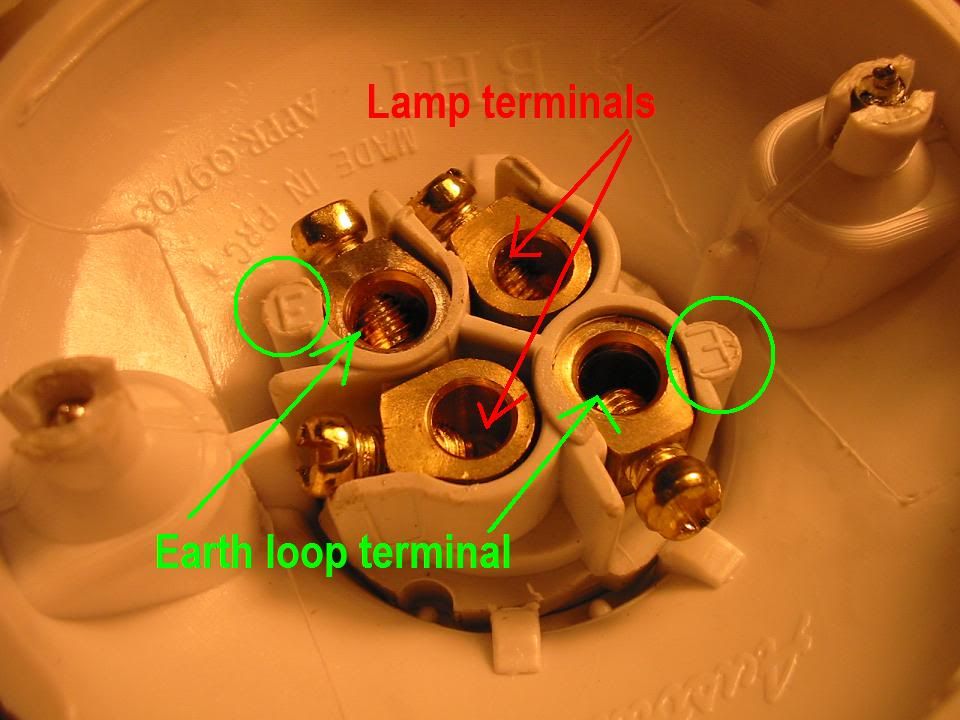
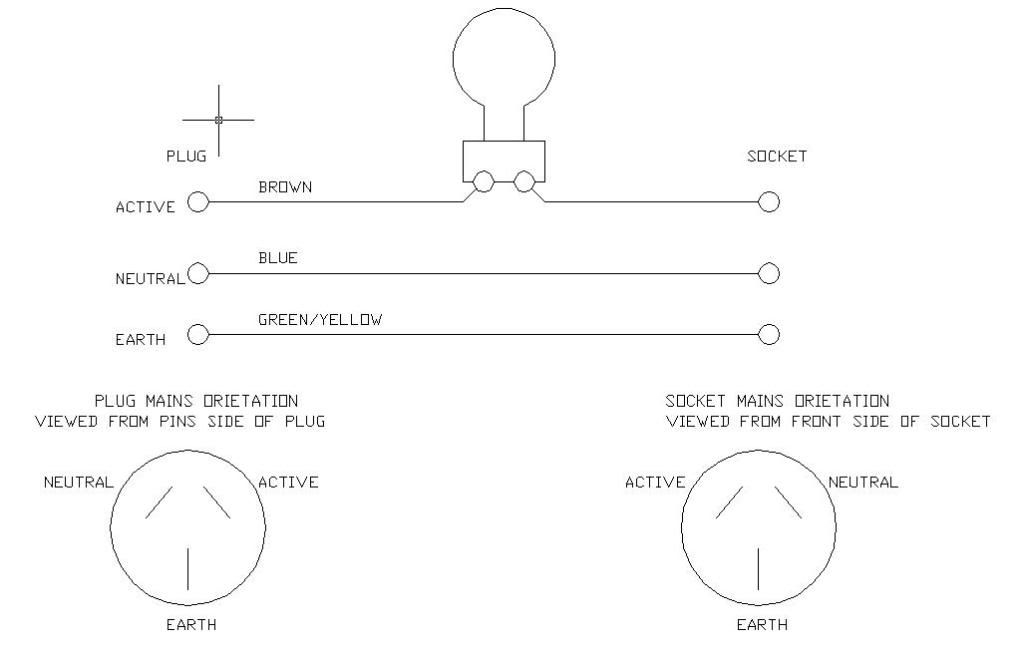
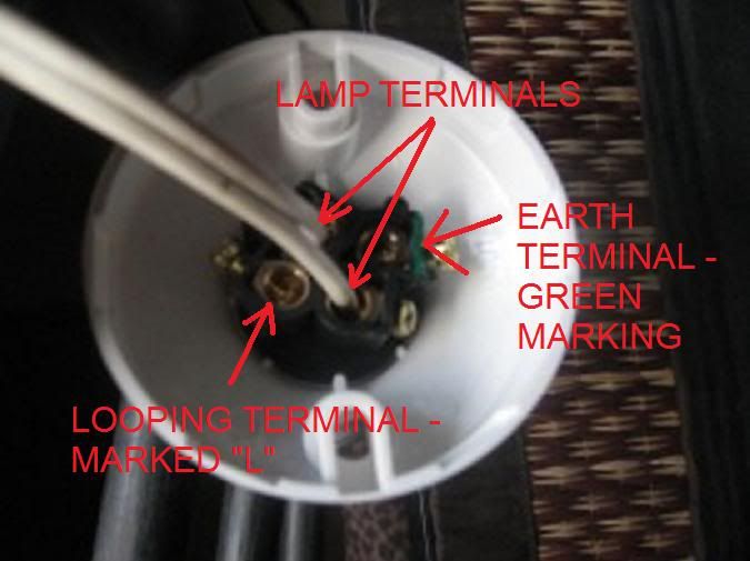
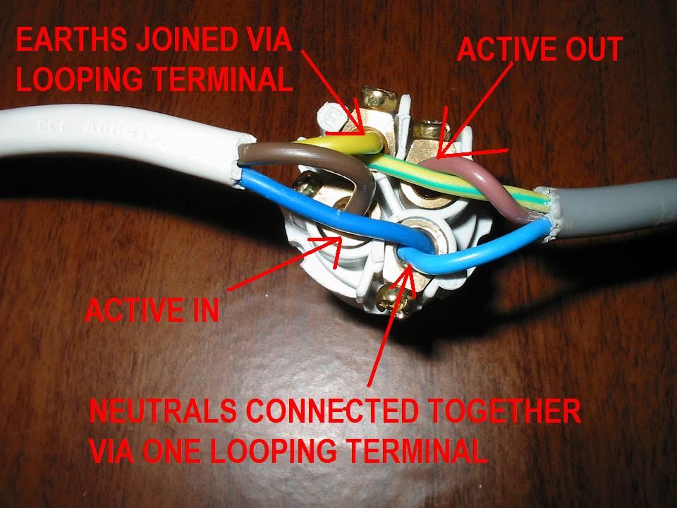
I changed the wiring over to what's shown in your picture, and everything seems to be working as expected.
With a 100w bulb:
Good amp, 15wpc - not a flicker from the bulb, amp powers up.
Suspect amp (turns out not), 40wpc - bulb lights at power up, dims quickly (less than 1 sec), stays off. Turning amp off and back on the bulb stays off. Leaving it off for a few minutes, then powering on, the lamp lights briefly, then dims. (This is like the youtube videos I found and what I was expecting).
(the really fun one) - a known bad amp. This is mid-90s BPC, supposedly 280w or so total. When powered on the protection circuit switches on and off rapidly (like twice a second). Putting this on the tester the lamp flicks on and off in time to the amps protection circuit. It's like a disco in my garage, with extra clicking sounds!
At that point I realised that a 100w incandescent bulb was probably a more valuable item than a 1990s receiver, so stopped risking my valuable bulb
.
The really dumb thing was that all this time a midge-type bug was hanging around looking at the bulb. So I'm not completely sure it has any repelling effect, but we'll see. Maybe the amp's power lamps were attracting it.
Also - just an aside on Post 20 - it may be an Australia vs US thing, but the wiring I was using earlier actually didn't trip the GFI. Just for what that's worth. I'm not sure if that's significant, but in case anyone else is accidentally replicating this