

You are using an out of date browser. It may not display this or other websites correctly.
You should upgrade or use an alternative browser.
You should upgrade or use an alternative browser.
Sansui AU 20000 restoration - many... many pictures
- Thread starter Kale
- Start date


EPI-Center
Super Member
I wish I had time to learn this kind of work, it is very interesting to me
thanks for sharing your talent and for preserving these classic pieces that need to live for another generation to experience.
thanks for sharing your talent and for preserving these classic pieces that need to live for another generation to experience.

Kale
Super Member
Haven't read the whole thread yet, but wanted to say to Kale that I have two different reg ps boards here and a couple of AU-20ks that have the output stages soldered on instead of the gold plug in pin assys.
I have had one BA3000 which has output stage wires soldered on the Motherboard, but until now I didnt see that on some AU20000
The same thing on that BA3000 was with bias transistorWe also know there are two different output stages, 1 with bias transistor on it, 1 without. Same for the driver boards, where the bias transistor moved from/to.
Last edited:
Kale
Super Member
@ DVNOBLE
YOU did great job, all those resistor changed by you is really a big work!
But I have some questions; why you didnt change trimmers on driver board, or as I can see you changed trimmers on one driver board, but with some open type. Those trimmers are so important (BIAS and DC Offset), so it will be the best if you use some multi-turn type.
And as second; why you didnt change those serial diodes with 1N4148 ?
YOU did great job, all those resistor changed by you is really a big work!
But I have some questions; why you didnt change trimmers on driver board, or as I can see you changed trimmers on one driver board, but with some open type. Those trimmers are so important (BIAS and DC Offset), so it will be the best if you use some multi-turn type.
And as second; why you didnt change those serial diodes with 1N4148 ?
Last edited:
Kale
Super Member
Nice work Kale, looks like the previous "technician, or butcher" used whatever screws they had lying around to secure one of the output transistors!!
I like the work you do to clean up the circuit boards, dismantle and clean the switches....
I also like those emitter resistors you are using.......
Thank you!
Those emiter resistors are 12Watt MILLS non-inductive resistors, and I like to use them at Sansui amplifiers - receivers


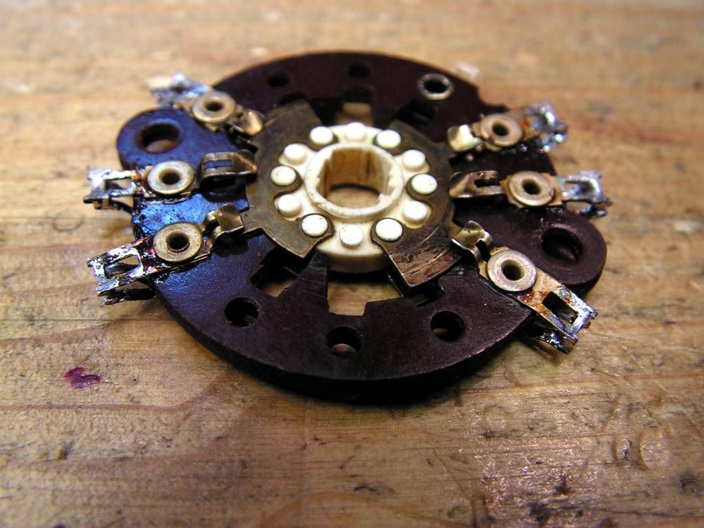
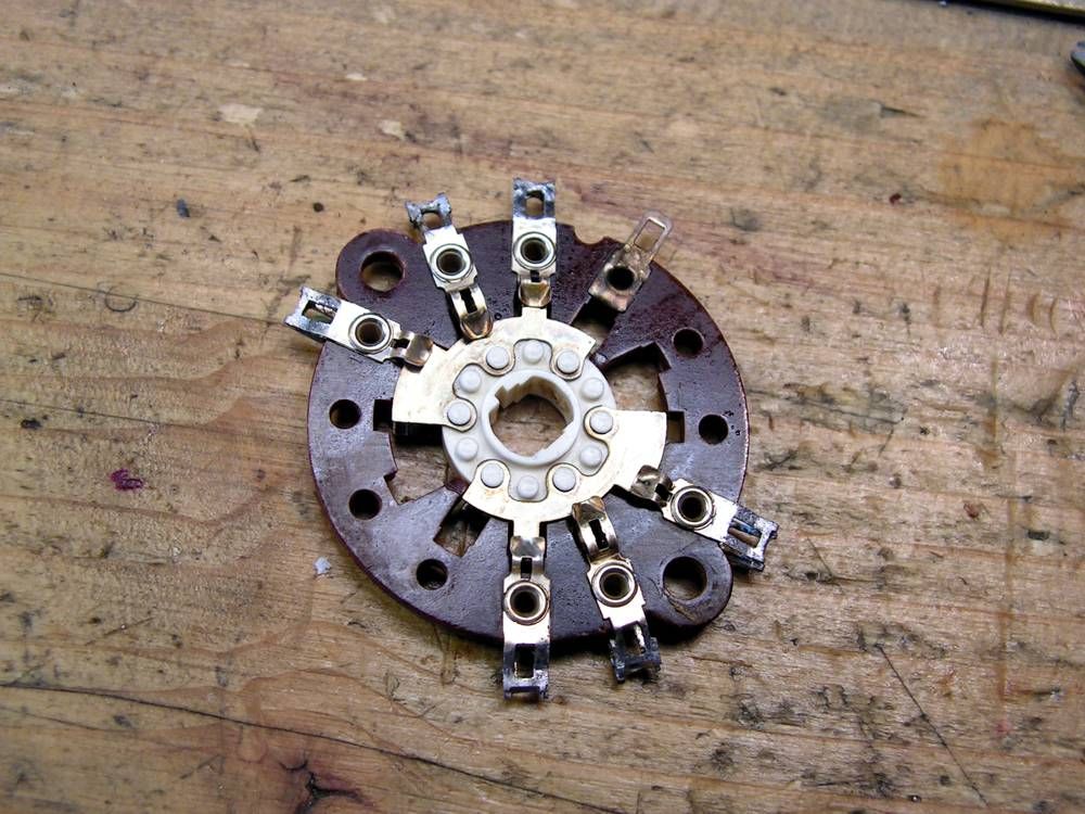
Kale
Super Member
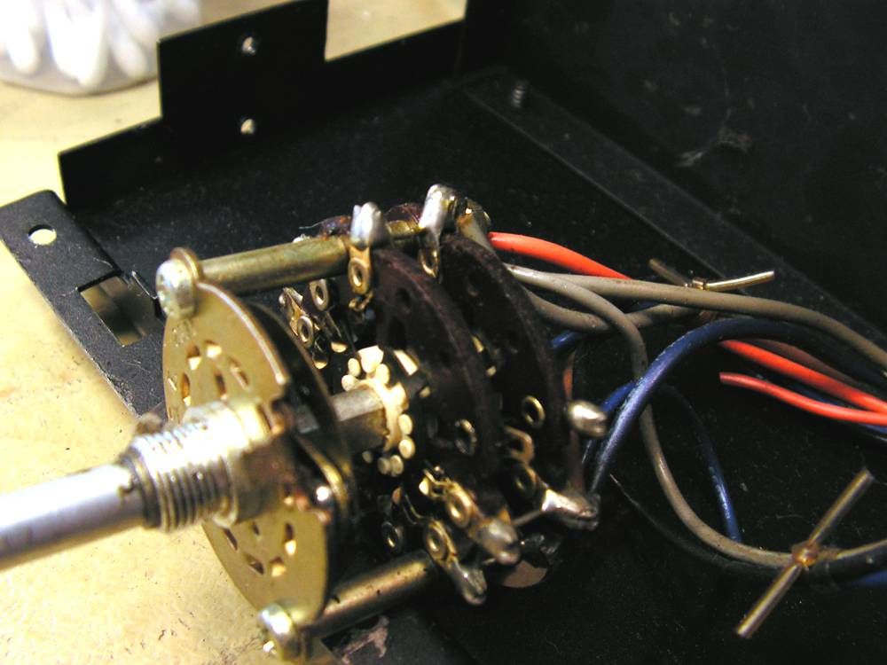
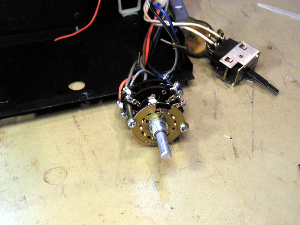
And now, Tape Copy Selector... but first you should see this
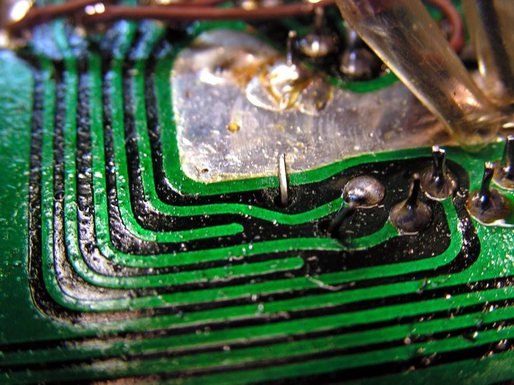
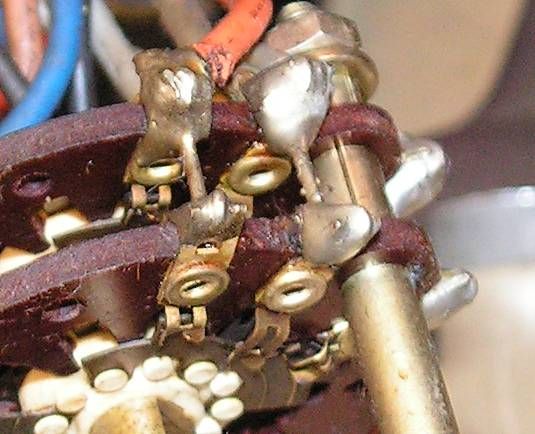
this is one unused pin of that selector, but it is bended on wrong way
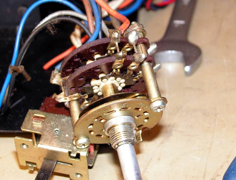
To dismount that selector, you should remove all small signal cables
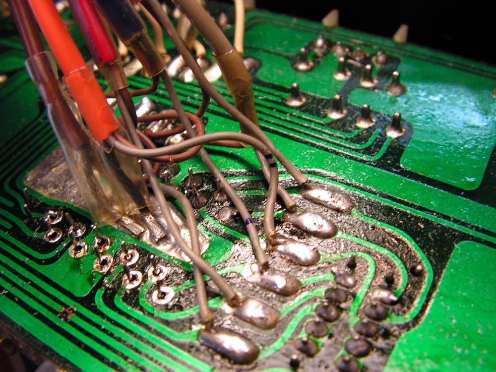
very demanding job...
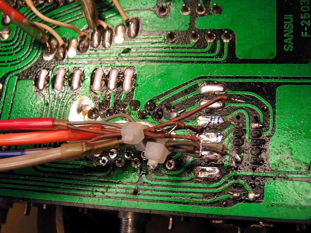
finally it is out
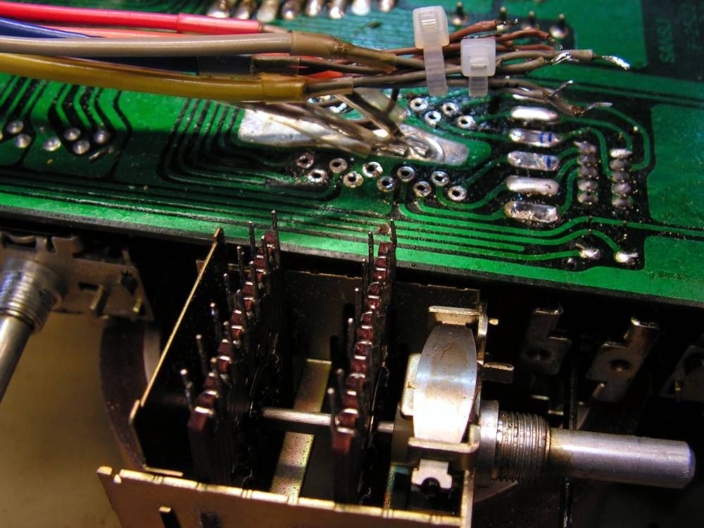
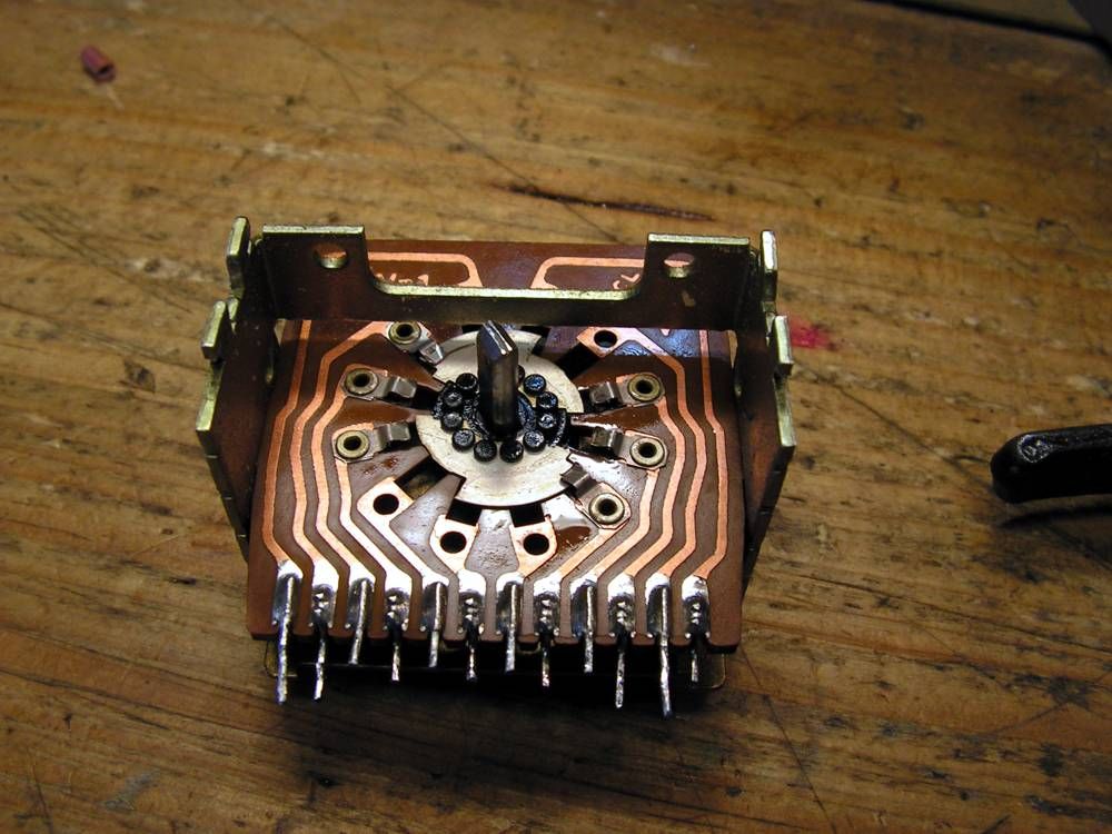
here you can see how it was looking
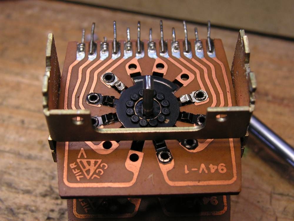
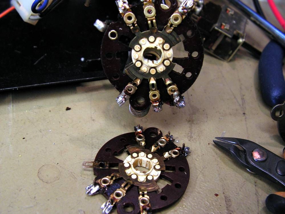
the both wafers ready for cleaning
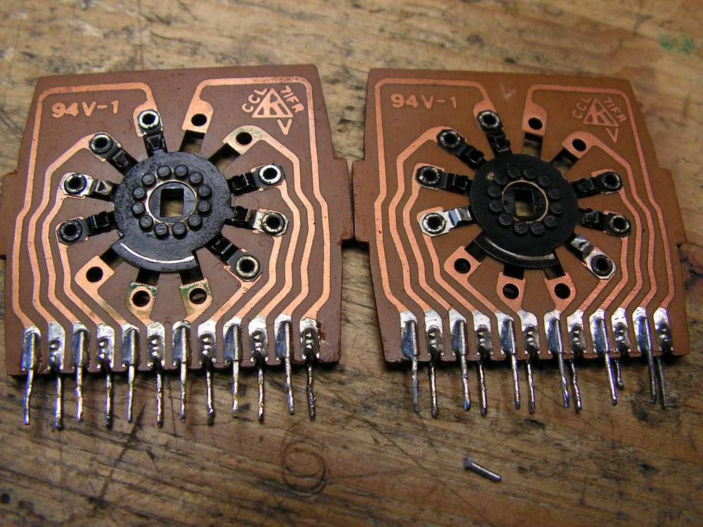
and like new...
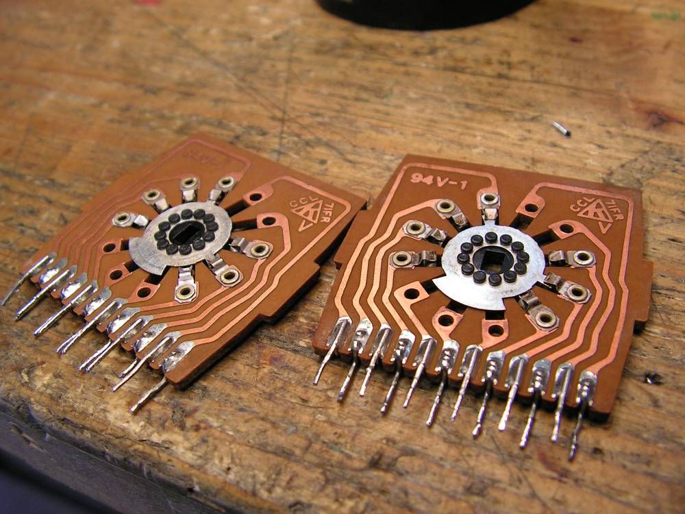
this is one unused pin of that selector, but it is bended on wrong way
To dismount that selector, you should remove all small signal cables
very demanding job...
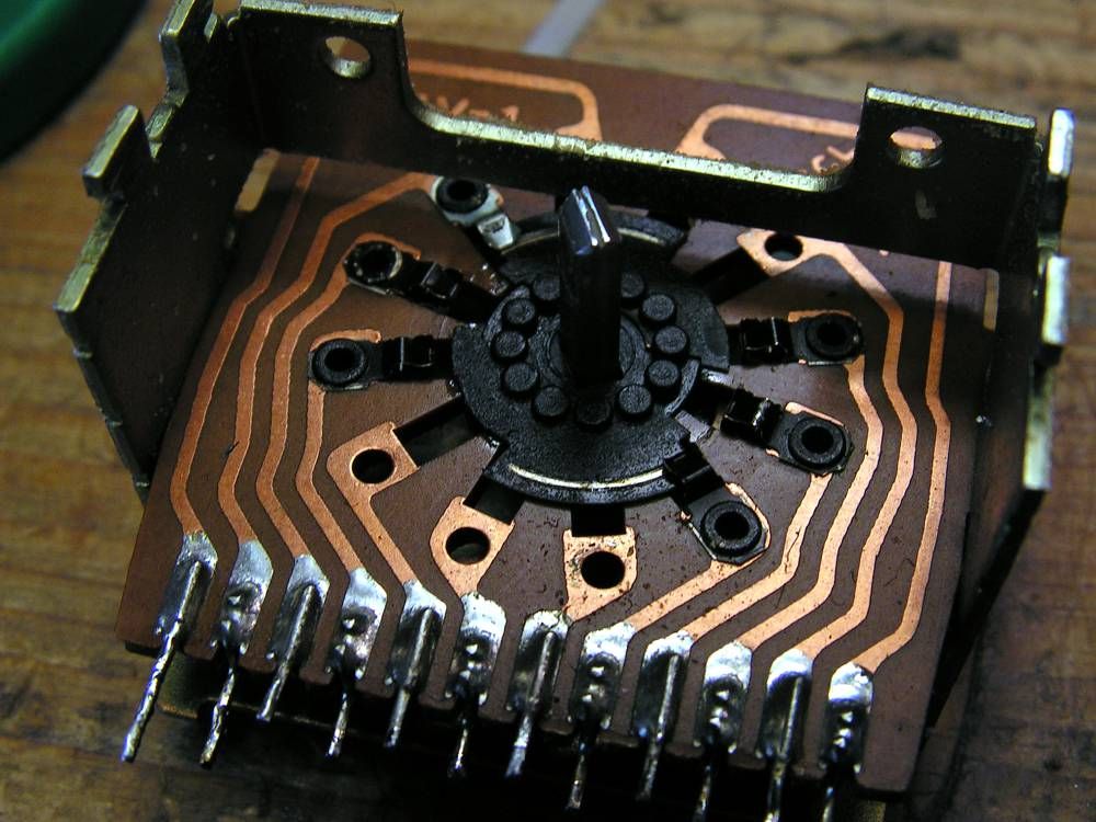
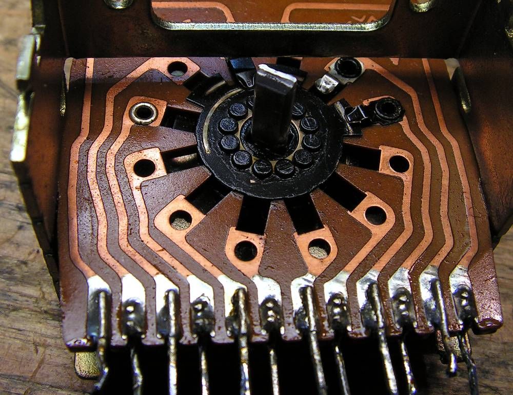
finally it is out
here you can see how it was looking
the both wafers ready for cleaning
and like new...

Kale
Super Member
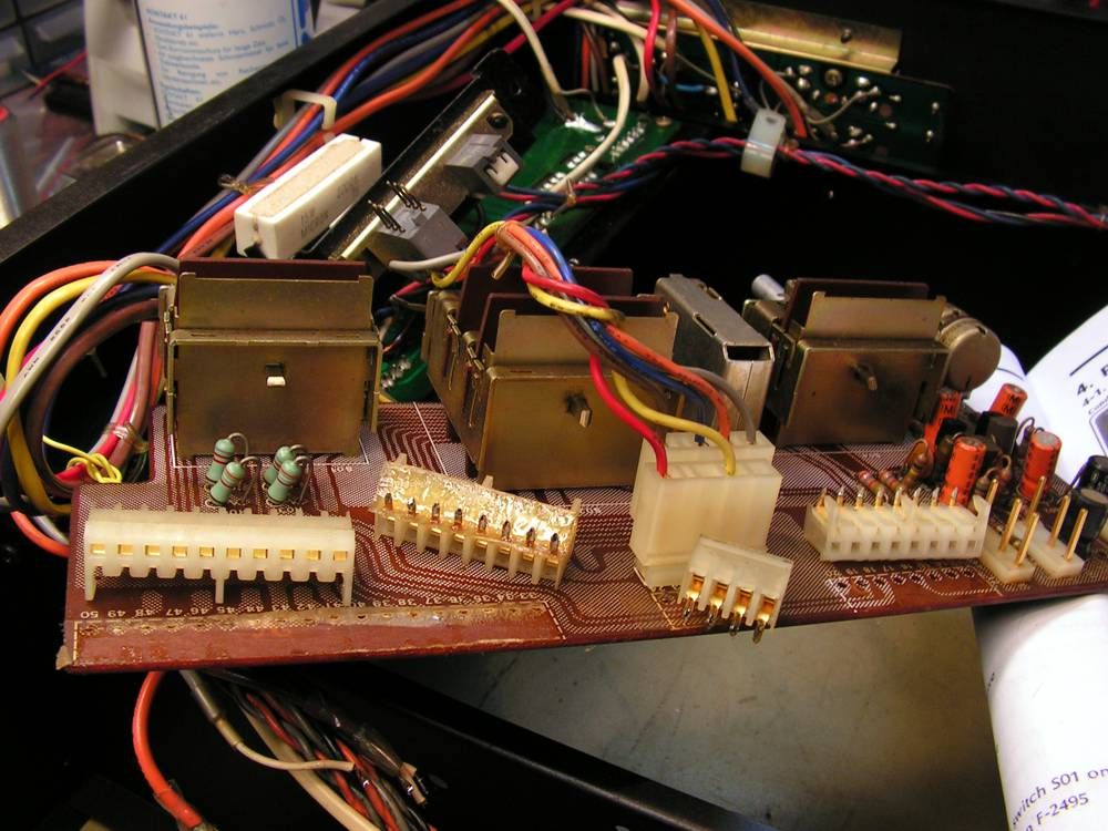
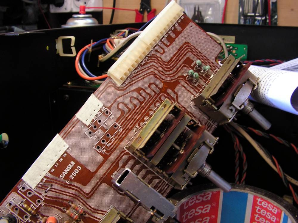
again cleaning.... cleaning... and again cleaning.....
here I have found a problem with Balance pot... it had a bad contact, but it is not simple to dismount it, look at the next picture :

the axle of potentiometer is nailed, and you should remove just only small part of that, just enough to separate the axle from other part of potentiometer.
Here you can see all parts of Balance potentiometer
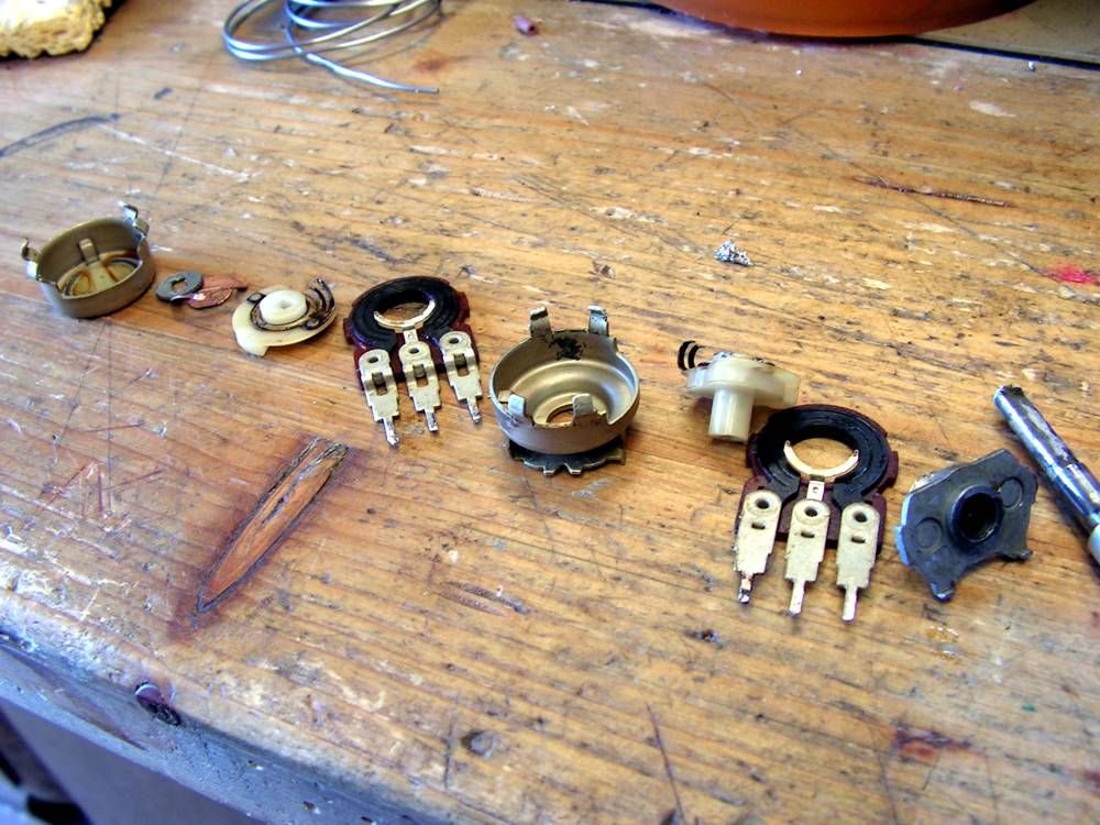
Now it is clear why it had bad contact

and again reassembled

and here it is, like a new
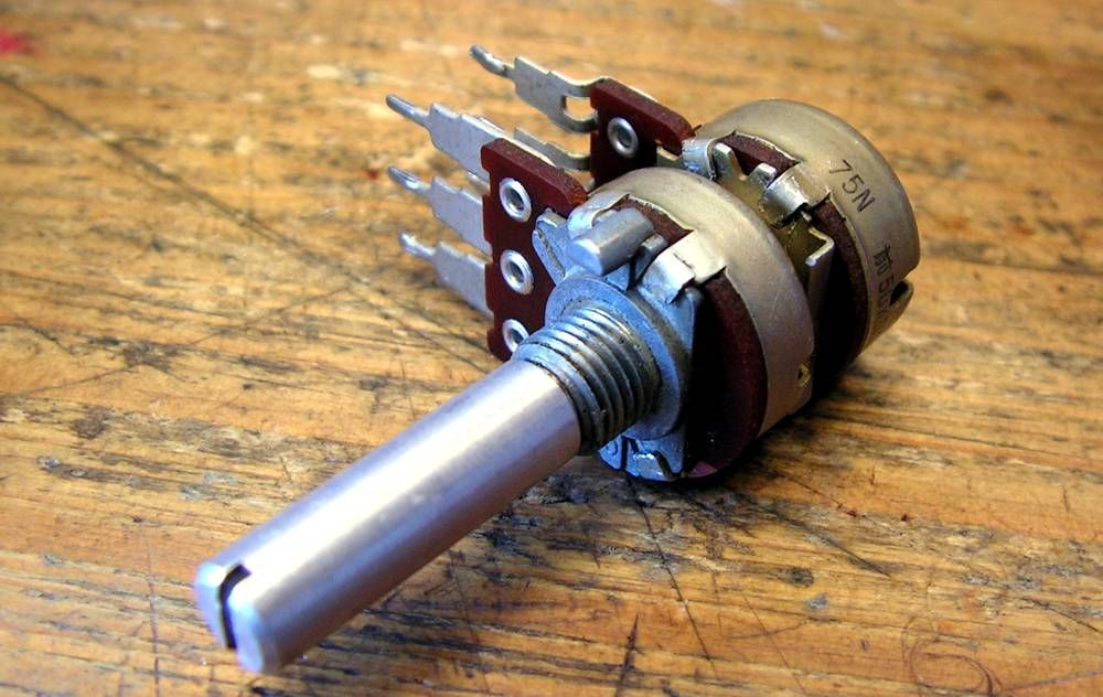
here I have found a problem with Balance pot... it had a bad contact, but it is not simple to dismount it, look at the next picture :
the axle of potentiometer is nailed, and you should remove just only small part of that, just enough to separate the axle from other part of potentiometer.
Here you can see all parts of Balance potentiometer
Now it is clear why it had bad contact
and again reassembled
and here it is, like a new

Man, somebody farked that amp up good. Just a shame what was done to it, and a blessing you ended up with it.
Where you get the NOS outputs?
Where you get the NOS outputs?
Kale
Super Member
Thank you John... but each day is harder and harder to do like these things, my eyesight is getting worse, so I do not know how long I will doing restorations on Sansuies...Kale, your work is so astonishing - sometimes it seems like you have brand new replacement parts (PCB's Switches etc) as the clean up job you do is so thorough.
Kale
Super Member
Where you get the NOS outputs?
From Japan, when the Yen wasnt so high like nowadays...
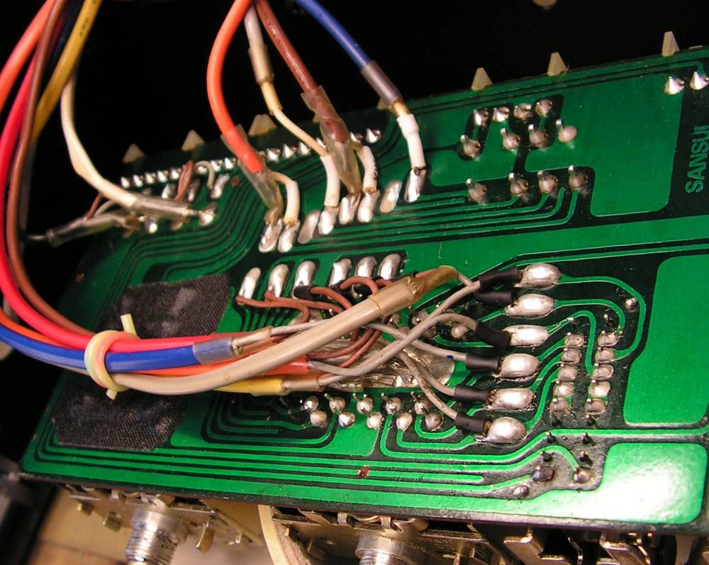
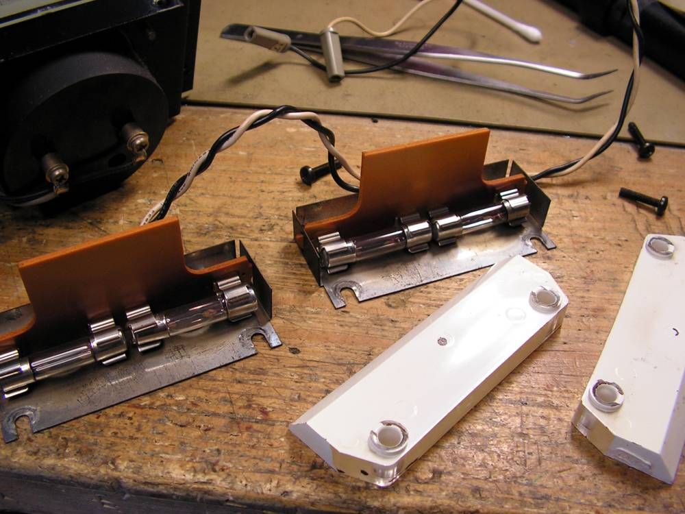
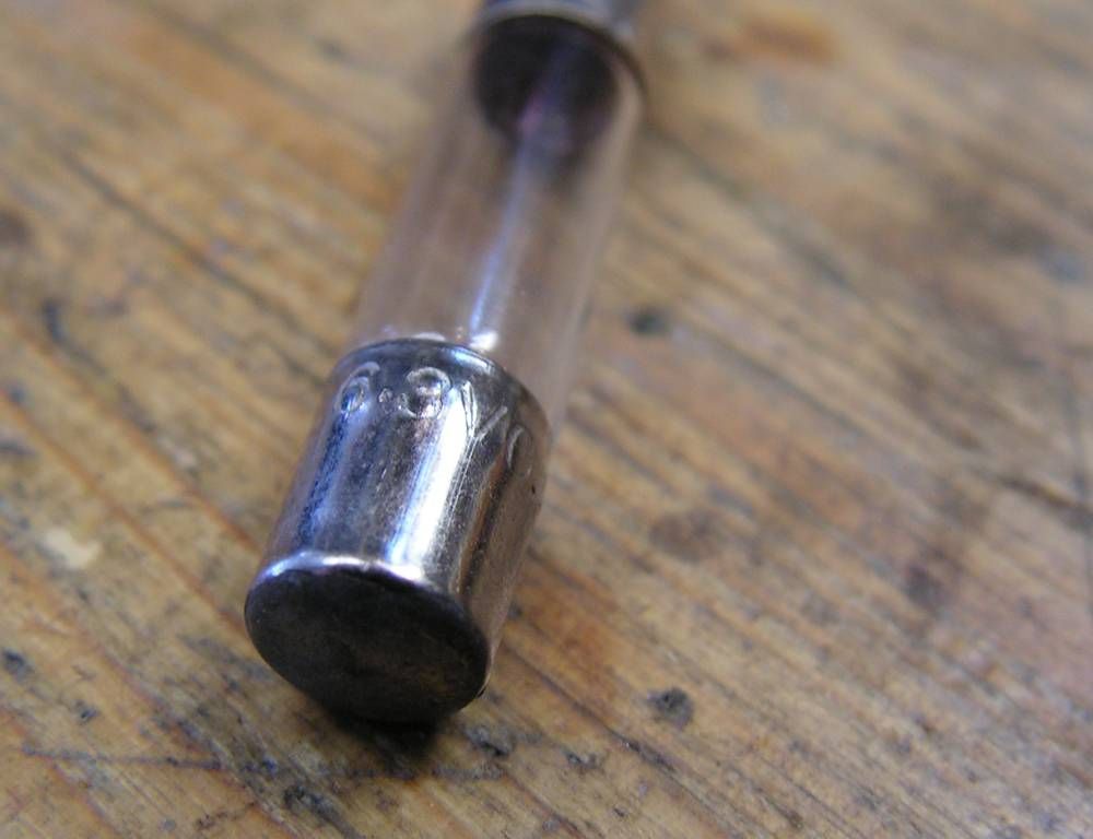


anderslober
Yikes...not again!
Hey Kale.........absolutely marvellous job! I was studying your pictures in post #32. On the meter circuit board......how did you orientate the capacitors that were in the wrong way? I noticed that you put 2 caps in the 'wrong' way and 1 cap(C03) in the 'right' way.....how do you know which is correct? The board.....or the cap? Which way do you trust?
GREAT JOB and GREAT STORY!
GREAT JOB and GREAT STORY!