• The move to the new server is done. There are some software and database maintenance updates in process. This has us passing the hat around to help out. We appreciate any donations. Seriously, even a dollar helps. The payment page may be found here - https://www.audiokarma.org/support.html

Twin MC75 refurb project next.

Pio1980

AK Member
Just finished a MC240 after doing a C24 for an elderly a'phile with a wall of tired malfunctioning Mac'. See thread here;http://www.audiokarma.org/forums/showthread.php?p=7188555#post7188555
The 75s have consecutive SNs and were purchased new in Binghamton by this first original owner. I will be doing all the e'lytics, the striper caps, and the bias PS. They also get new inrush MOVs and what-ever else pops up like loose sockets, ect.
These 3 pieces are my first tubed Mac experiences, I do have a MC50 as my only owned Mac piece that has been basically a pretty doorstop since acquired, being a mono unit overqualified for anything I'd need for that service.

After these will come an MR71 and MX110 which I hope won't need alignment as I cannot do FM alignments.
 
Register to hide this ad
PIO1980, all of the Mac amps of this vintage are pretty much the same for how to get the best out of them. Rodeodave's link is a good time capsule of what to do and which roads not to take.

They're great amps, simple in design, brilliant in their performance.

Cheers,

David
 
What dropping resistor value is appropriate for the selenium-to-silicon replacement diode rectifier in the MC75?
 
Hey PIO, I was thinking about PS caps, and posted on that MC30 thread where you asked what I used - but figure I'd say this in a more appropriate thread ...

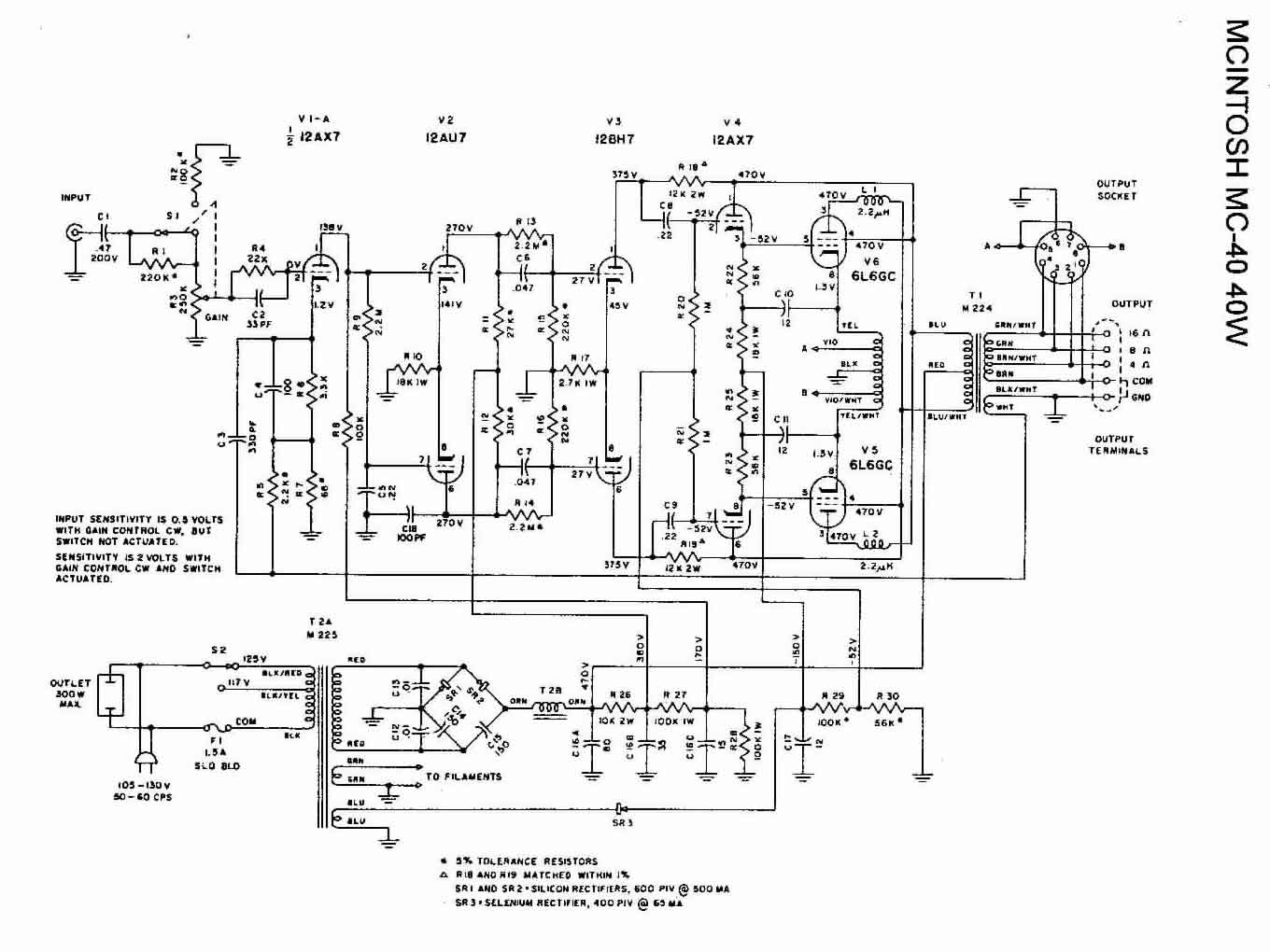
The paper manual for my MC40s shows that in later serial numbers, the 470v and 380v supplies are combined (and two resistors in the signal path change values, to compensate for getting 470v instead of 380v). The 10K resistor (in the PS) which drops the 470v to 380v goes away, and some capacitors become effectively combined.

The MC75 PS looks virtually identical to me. The corresponding change would eliminate R29 and combine the 460v and 380v supplies, and R11 and R12 values would increase. Why go to this trouble ? Because C15A, C15B, and C16A could all be combined, and you no longer need multi-section cans: you can choose from a variety of cheap options (JJ, F&T, snap-ins from Panasonic and others) used with can clamps. You still need C16B, but it's only 30uF and a lower voltage, so you can use a cheap axial lead part for it.

Obviously you shouldn't do this based on my conjecture, but I'd be VERY surprised, if you could find a later version of the schematic, if it didn't show such a change. I attach a snippet of the schematic for my MC40, which shows the later model with the change, with the dotted lines showing the older version. NOTE2 says that R26 goes away, and NOTE5 says that R27 is now 100K.

The same thing almost certainly applies to the MC240.

Anyhow, just a thought ...

P.S. Of course (smacking forehead and saying "duh !") this may be exactly what you were talking about, over in the "family heirloom MC30" thread.
 

Attachments

  • Screen Shot 2013-10-30 at 2.51.16 PM.png
    Screen Shot 2013-10-30 at 2.51.16 PM.png
    69.6 KB · Views: 97
Last edited:
Hey there!
Thnx much for the feedback and opportunity to discuss this project.
I'm more a 'nuts-and-bolts' sorta guy with these things, the driver/output stages are beyond my present understanding of the theory of operation so I'm avoiding going too far astray.

The power distribution in the MC30 according to the skiz is pretty primitive with no interstage B+ rail filtering.
McIntoshMC30.jpg

The later amps look more sophisticated, the MC40, MC240 and MC75 have a full-distribution isolation network for the stages with the output right after the choke on the C-L-C pi portion which appears to be good practice as to separate that stage from the earlier stages.
McIntoshMC40.jpg

An improvement should be to shunt each portion with a film cap across each of the filter elyticaps as long as instability doesn't result as an unintended consequence. The '40 should also probably have a surge suppressor on the primary side of the PT.
As far as the MC-40 goes, it appears similar to the '240 and '75 on the PS, so combining the caps would appear to lose some interstage isolation that may or may not change something that matters. Regardless, more modern caps with film shunts should provide more effective isolation higher up than the older components. There will also be an issue with some Mac folk about upgrading/mod'ing vs preserving the McIntosh "sound". As these aren't mine that isn't an issue, simply restoring their proper original functionality will satisfy the owner and should a classic Mac stereo amp someday find me I will have those decisions to make re my own priorities vs what is best for it should I decide to keep it to use.
 
Last edited:
As far as the MC-40 goes, it appears similar to the '240 and '75 on the PS, so combining the caps would appear to lose some interstage isolation that may or may not change something that matters. ... There will also be an issue with some Mac folk about upgrading/mod'ing vs preserving the McIntosh "sound".
I am NOT talking about a modification. The official McIntosh manual that came with my MC40 shows the circuit with the PS cap (C16 A &B) combined and the 10K resistor (R26) deleted. The version that you posted above (and which is the version which seems to be readily available online, at sites such as www.tubebooks.org), is shown in my manual as being for "serial numbers below 428L7", and referenced via dotted lines and notes.

I take this as meaning that McIntosh considers that older circuit to be obsolete, so presumably they didn't think the newer circuit changed something that matters and that it preserves the McIntosh sound. I certainly hope that's the case - and if anyone knows it not to be, PLEASE chime in - as I intend to convert my pre-428L7 amp to the post-428L7 circuit when I rebuild the PS's soon.

I've attached a scan of my manual. I'm very curious as to whether or not the manuals for the MC75, MC240, etc show the same circuit variants.
 

Attachments

Last edited:
You would think if it's good for the '40, why not the others. Thnx for the manual, will get into it.
So, being P/P pretty much thru-out, common-mode rejection of PS rail cross-talk would render the later implementation basically as the first but with simpler part source requirement, at least in theory.
Wonder if that was their thinking on the MC30 tho' it's front end voltage gain stage is also single-sided class 'A' which essentially has no inherent PS noise rejection.
 
Last edited:
You would think if it's good for the '40, why not the others.
Yeah, but I wouldn't do it without seeing a document - like the one I attached above - that shows such a circuit. Surely somebody has a copy of the MC75 manual.
Wonder if that was their thinking on the MC30 tho' it's front end voltage gain stage is also single-sided class 'A' which essentially has no inherent PS noise rejection.
It's such a different circuit - what with the vacuum tube rectifier - that I wouldn't presume to think the same circuit variant would be reasonable.
 
Yeah, but I wouldn't do it without seeing a document - like the one I attached above - that shows such a circuit. Surely somebody has a copy of the MC75 manual.

It's such a different circuit - what with the vacuum tube rectifier - that I wouldn't presume to think the same circuit variant would be reasonable.

I can't say as the only manuals I can access are on-line an and whatever the owner may have. The larger reservoir capacity can benefit the output stages LF and instantaneous output performance.

There should be little difference between the PS characteristic after the choke/cap other than the inrush charging surge of the silicon doubler version vs the soft-start of the tube rectifier, tho' the silicon may present a 'firmer' current source. The front end in the amended MC40 is still pi-filter-isolated where it would be most critical, so the revision makes good practical sense considering the common-mode rejection of the following balanced /P-P stages. Applying the front-end filter isolation to the MC 30 is do-able and probably advisable as an upgrade, the value of the input reservoir filter cap is limited by what the tube can tolerate as warm-up surge current, I think 40uF is pretty much it.
 
Last edited:
It's very difficult to find the version of the MC40 schematic which shows the circuit variations. Most just show what is considered the "old" version in my manual. But I found a site:

http://www.kbapps.com/audio/schematics/tubeamps/mcintosh/index.php

... which has the version of MC40 schematic with the variations. Unfortunately I am unable to locate online (I have it on my computer, and attached it in post #10 above) the PDF of the entire manual, which shows what NOTE2, NOTE5, etc mean.

Anyhow, at the kbapps page, check out the schematics for the MC240 and MC275, which have dotted lines and notes showing somewhat similar variants of the PS circuit.

Also note that the schematic for the MC30 shows no such "ambiguities" in the PS circuit. So I'm guessing McIntosh never officially sanctioned such a mod. Therefore, I'd be very reluctant to do it, since there's an unknown downside (unknown unless you understand the circuit a lot better than I do, which you sound like you may), and very little upside that I can see. The only reason I'm changing my older MC40 is so mine will be identical, which I think will make life simpler going forward, and also eliminates the need for any multi-sections cans (assuming one doesn't mind using a separate axial-lead part for the smallish cap on the 100+v supply rail).
 
Last edited:
Chuck, what exactly is your non-textual post supposed to mean ? It seems to me that it's kinda of a snarky response suggesting that the conversation is a silly one, and you're gonna get a bag of popcorn and sit back and watch it like an entertaining, if not particularly good, movie. Do I misunderstand ? Am I, or PIO, coming off as a troll ? I genuinely want to know. Thanks.
 
I'm a "nuts-and-bolts" kinda guy with these things tho' I do appreciate theory of operation, but these are honestly somewhat beyond my ability to "globally" understand how the driver/OP stage works.
Certain things are common practice and the later versions reflect that, shielding the front end, particularly if single-ended class-'A', is common practice as any pumping of the DC PS rail with shift the operating point of the front end voltage amp stage. This will definitely show up in the output as LF/VLF instability/IMD, particularly under stressful cdx. Think full-range pipe organ recordings into AR-3A at rated output F.I..

It's very difficult to find the version of the MC40 schematic which shows the circuit variations. Most just show what is considered the "old" version in my manual. But I found a site:

http://www.kbapps.com/audio/schematics/tubeamps/mcintosh/index.php

... which has the version of MC40 schematic with the variations. Unfortunately I am unable to locate online (I have it on my computer, and attached it in post #10 above) the PDF of the entire manual, which shows what NOTE2, NOTE5, etc mean.

Anyhow, at the kbapps page, check out the schematics for the MC240 and MC275, which have dotted lines and notes showing somewhat similar variants of the PS circuit.

Also note that the schematic for the MC30 shows no such "ambiguities" in the PS circuit. So I'm guessing McIntosh never officially sanctioned such a mod. Therefore, I'd be very reluctant to do it, since there's an unknown downside (unknown unless you understand the circuit a lot better than I do, which you sound like you may), and very little upside that I can see. The only reason I'm changing my older MC40 is so mine will be identical, which I think will make life simpler going forward, and also eliminates the need for any multi-sections cans (assuming one doesn't mind using a separate axial-lead part for the smallish cap on the 100+v supply rail).
 
Here's a pic of the first PS refurb with the blue Sprague 330uF/ 250V snap-in caps for the doubler bridge, the bias supply and signal board is next.
attachment.php
 
Looks good. I think I'm going to use RTV-silicon (instead of clamps, though I keep going back and forth on it) to attach my snap-ins (on MC40).
 
Back
Top Bottom