• The move to the new server is done. There are some software and database maintenance updates in process. This has us passing the hat around to help out. We appreciate any donations. Seriously, even a dollar helps. The payment page may be found here - https://www.audiokarma.org/support.html

The Disappointment That is the Heath W4

Steve O

Super Member
Awhile back there was a discussion regarding OPT replacement for a Heath W5 amp (Linked Here). During the discussion the topic veered away from the W5 to the W4 and its deficiencies esp WRT to stability and HF performance. During that discussion I commented on how I found the W4s I have are unstable with the stock circuit esp at HF and would actually break into sustained oscillation if a resistive load was paralleled with a 1uF cap. I also posted a schematic with my fix for the HF instability.

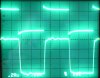
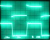
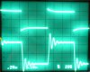
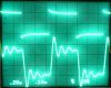
I decided to take one of the amps off the shelf and run some sq waves thru it to illustrate the problems I found with the stock circuit. I took pics of scope traces on both stock and modified circuits with 8 ohm load and 8 ohm || 1uF load. Signals were 1KHz and 10KHz sq waves. Horizonatal scale is in uncal mode to get a few cycles on the screen.

The first set of pics shows performance with straight resistive load, stock and with mods. Although the 1KHz patterns don’t look too bad, the stock circuit definitely has some delayed overshoot and ringing compared to modified. At 10KHz, differences are more apparent. The stock circuit appears to be ringing @ ~200KHz. Although I thought the stock circuit sounded edgy I probably would have accepted this level of performance if this was all there was to it. However……..

attachment.php


The second set of pics show what happens when 1uF is placed across the load resistor. As is apparent, the stock circuit has broken into sustained oscillation @ ~70KHz. Surprisingly, the sq wave is is still reproduced… somewhat. Without an input signal the amp oscillates @ 75KHz / 5V P-P. IMO, this is absolutely unacceptable performance and disqualifies the amp for use in a music system. Incredibly, Heath apparently was aware of the issue since they recommend that only low capacitance speaker cable be used and never use coax.

Although the modified circuit isn’t pretty, esp @ 10KHz, at least it isn’t oscillating. Ringing occurs @ ~ 30KHz . Stock response is specified as extending beyond 100KHz @ a couple of dB down. Modified response is nowhere near as extended being flat to ~20KHz and –0.3dB ~25KHZ but falling rapidly after that.

attachment.php


As I noted in the previous thread, my original objective with the W4 was unconditional stability and improved sq wave response. Sound was also improved as the edginess was greatly reduced. After revisiting these amps and the mods, if I were to redo things, I would probably accept a little more ringing to extend the HF a bit. I would also address another flaw in the W4 I discovered while putting together these images: a rather pronounced LF instability. Miniscule perturbations in line voltage or signal transients would produce a LF bounce in the output signal of ~0.5 V P-P that would continue for a couple of seconds after the disturbance had ceased. Although there are some changes that can be made to the circuit that can reduce the LF instability, as I opined before, I believe most of the problems with the W4 arise from use of an OPT that is simply not up to the task. If I replace the OPT with something markedly better (and probably mucho $$ more expensive) I probably no longer have a W4 so why bother?

Bottom line from my perspective: The stock W4 is poorly designed and spec’d and probably should not be a part of a real-world music system. This is esp so if the speaker load is reactive or if fancy, high capacitance speaker cables are to be used. The gold version is pretty in its own 50’s industrial sorta way and would make a nice conversation-starting display piece.

All of the above is of course JMHO.
 

Attachments

  • Heath W4 Pg 2.jpg
    Heath W4 Pg 2.jpg
    61.4 KB · Views: 383
  • Heath W4 Pg 1.jpg
    Heath W4 Pg 1.jpg
    58.9 KB · Views: 398
Last edited:
Register to hide this ad
Nice write-up Steve. Makes me want to put the W4 on the bench and see what I can do. Some day:scratch2: I bet though, that if you put a good deal of other amps through these tests, that they would have similar or other problems that stick out as well.
 
Nice write-up Steve. Makes me want to put the W4 on the bench and see what I can do. Some day:scratch2: I bet though, that if you put a good deal of other amps through these tests, that they would have similar or other problems that stick out as well.

Considering just the stability issue, the following amps pass the test in stock form albeit with varying degrees of sq wave beauty (not a comprehensive list, just those I have experience with):

McIntosh
MC30
MC40
MC60
MC75
MC225
MC240
MC275

Marantz
8B

Heath
W5
UA1/2
AA100
AA151

DuKane
1A475

Fisher
80AZ
400
500C

Quad
Quad II

Craftsmen
C500A

RCA
MI 4188


Dyna
ST35
ST70
MKIII (rings excessively but at least it doesn't oscillate)

HK
Allegro (dirt cheap mono integrated w/tiny opt and positive FB within OA neg loop)

Knight
KB85
83YX797 (another cheap mono integrated amp)

Point is that stability was no mystery back in the day. Even Heath could do it. It's when the mfgr decides to cheap out somewhere that problems arise. Curiously, if one "generic" design stands out as prone to stability issues it's the lower cost implementations of the "Williamson".
 
The W4 wasn't designed to be the be-all end-all amp of the century, it was a budget consumer amp made to be something most people could afford, another reason it was a kit. Hard to compare it with the line of McIntosh amps:sigh:. And, 1uF is a lot of capacitance, especially when most cables probably average under 50pF/foot. I'm sure the speaker wire of the day never included braided CAT5 stuff. And, when it doesn't have a 1uF capacitor on it, it sounds pretty great:D

I don't know why I'm sticking up for this amp...maybe for the many people that have enjoyed it over the past 60 years...were they all wrong to??:scratch2:

The stock W4 is poorly designed and spec’d and probably should not be a part of a real-world music system.
I can understand reviewing and critiquing a new amp, but this is a 60yr old design?? Poor Mr. Heath, Anthony, Daystrom... :tears:
 
I actually did test waveforms on one of my W4s, and they looked quite different from Steve's. For mine, the ringing on the 10KHz squarewave (w/no cap) was damped away after a few HF cycles, there was no continuous oscillation. The same goes for adding a capacitance up to about 0.33uF. However, it still oscillated with 1uF. Perhaps the new parts installed affecting things?

I have installed new metal films for most of the resistors, new electrolytic caps for power supply and cathode bypass, and NOS weston PIO caps for coupling. Input tube is a tung-sol 6SN7WGT, driver tube is sylvania chromedome 6SN7GTB, and output tubes are old stock RCA (tung-sol) 5881s.
 
hey-Hey!!!,
Seems the W4 was inbetween two models with better outputs, the W3 with its Acrosound TO-300 and the W5 with its Peerless 16458 and 16309. They both have the same Williamson circuit and FB path. It would be quite easy to apply balanced FB to the driver stage grids from the output tube's plates; that circuit just begs for it IMO.
cheers,
Douglas
 
I actually did test waveforms on one of my W4s, and they looked quite different from Steve's. For mine, the ringing on the 10KHz squarewave (w/no cap) was damped away after a few HF cycles, there was no continuous oscillation. The same goes for adding a capacitance up to about 0.33uF. However, it still oscillated with 1uF.

<snip>

On my test amp the 10KHz sq wave ringing was merely poorly damped, not continuous.

<snip>

Perhaps the new parts installed affecting things?

I have installed new metal films for most of the resistors, new electrolytic caps for power supply and cathode bypass, and NOS weston PIO caps for coupling. Input tube is a tung-sol 6SN7WGT, driver tube is sylvania chromedome 6SN7GTB, and output tubes are old stock RCA (tung-sol) 5881s.

On my amp I replaced all electrolytics and out-of-spec CC resistors. Repl resistors were MF in direct signal path or MO in PS sections. All coupling caps were replaced with 715P orange drops @ orig values. Tubes are used/test good RCA 6SN7GTA, RCA 5V4G and Sylvania 6L6GC.

Some possibilities for the differences we find betw our test results:
1. My OPT is defective. I'd expect to see this manifest itself in a freq sweep that doesn't meet orig specs. I can't find the one I originally ran so I guess I'll do it again.
2. My circuit dress is sloppy. As it is, it follows the Heath L/O pretty much to the letter.
3. Your sq wave signal rise time is considerably greater than mine and/or your amp has some sort of input LP filtering, either intentional or inadvertent.
4. Test load is different from what I used (8 ohm NI resistor on 8 ohm tap). What load did you use for test purposes and on what tap did you place it? Since the W4 takes feedback from 16 ohm tap, I would expect much improved meas perf if 16 ohm tap is used with 16 ohm load.

Although this amp doesn't warrant a whole lot of addl effort, I AM curious as to the cause of the discrepancies betw our test results. Got any pics or response plots to post?
 
hey-Hey!!!,
Seems the W4 was inbetween two models with better outputs, the W3 with its Acrosound TO-300 and the W5 with its Peerless 16458 and 16309. They both have the same Williamson circuit and FB path. It would be quite easy to apply balanced FB to the driver stage grids from the output tube's plates; that circuit just begs for it IMO.
cheers,
Douglas

If you look at the suggested retail prices in 1960, it becomes clear that the W4 was the budget version of the Heath Williamson series. W3 = $49.75, W4 = $39.75, W5 = $59.75. Price aside, I still kinda expect the W4 to be a better performer than mine are.
 
On my test amp the 10KHz sq wave ringing was merely poorly damped, not continuous.

I simply meant in the window on view with the 10KHz sq wave (50uS), it appears as if it is continuous.

Some possibilities for the differences we find betw our test results:
1. My OPT is defective. I'd expect to see this manifest itself in a freq sweep that doesn't meet orig specs. I can't find the one I originally ran so I guess I'll do it again.
2. My circuit dress is sloppy. As it is, it follows the Heath L/O pretty much to the letter.
3. Your sq wave signal rise time is considerably greater than mine and/or your amp has some sort of input LP filtering, either intentional or inadvertent.
4. Test load is different from what I used (8 ohm NI resistor on 8 ohm tap). What load did you use for test purposes and on what tap did you place it? Since the W4 takes feedback from 16 ohm tap, I would expect much improved meas perf if 16 ohm tap is used with 16 ohm load.

Same here with the 8-ohm load resistor on 8-ohm tap (20Watt radio shack type 'NI' ww). I'll post scope pics when I get home from work. I can also take lead dress pics, though there are some right here: http://gregory.webng.com/W4/W4AM.html

wait, I can think of one thing that is different from stock...I removed the input AC coupling cap. This may or may not have any effect on sq wave performance. If it does turn out that this cap has this much of an effect, well then we have our easy fix right there.
 
Steve, I notice you are using the RCA 6SN7s, while Bricktop is using a Tung-Sol. My ears have suggested to me that the RCAs (and also Russian and GE tubes) have lower transconductance than the TS / Sylvania tubes when used in the first stage of the Williamson (loose and sloppy sound vs. tight and fast sound, suggesting reduced feedback by reduced open loop gain). My hypothesis is that some 6SN7s don't perform as well at lower voltages, and in the case of the W4, the first stage has around 60V on the anode (worse than typical Williamsons ~90V). This might sound like crazy audiophool guesstimation, but perhaps you could try swapping a Sylvania or TS in for the first stage, to see if things improve slightly? I'm wondering if the difference in gain for the first stage is throwing off the feedback tuning. Crazy notion, and I am probably be completely wrong, but might be worth a go! ;)

At least, my Craftsmen amps sound rather "broken" with an RCA / GE / EH in front, but a-okay with a Sylvania / TS / Raytheon -- the driver stage is obviously less critical. I haven't taken the time to measure this, but usually there's a way to "see" what you can hear.
 
Here are the waves. 8-ohm load on 8-ohm tap. The input wave looks screwy but it is actually flat, I measure it with a compensated probe to check. It's just hooked up with coax test leads in the pics. The output is measured with a compensated probe (10x) in the pics. Waves aren't too bad, definitely different at 10KHz. It should be noted that the wave looks much better on the 16-ohm tap, where feedback is derived. A good tweak to do if using only the 8-ohm tap might be to change the feedback network to that tap. This might help things out a bit, but I'm happy with it right now. Also, if the square wave is band-limited to under, say 40KHz, there is no ringing on the output, only a nice reproduction of the input. So if your using it for music (which I think most everybody is), then it's fine.

Good bathroom reader on stability from the pmillett site: http://www.pmillett.com/file_downloads/moyle_amp.pdf

And for those interested I measured distortion:
Heathkit W4-AM
Measured with Hp 8903A
------------------------------
Power | Frequency | THD
------------------------------
1 Watt | 20 Hz | 0.30%
1 Watt | 100 Hz | 0.060%
1 Watt | 1 KHz | 0.049%
1 Watt | 10 KHz | 0.20%
1 Watt | 20 KHz | 0.50%
--------|-------------|-------
10 Watt | 20 Hz | 0.40%
10 Watt | 100 Hz | 0.27%
10 Watt | 1 KHz | 0.22%
10 Watt | 10 KHz | 0.90%
10 Watt | 20 KHz | 2.81%
 

Attachments

  • 1KHz.JPG
    1KHz.JPG
    177.7 KB · Views: 85
  • 10KHz.JPG
    10KHz.JPG
    179.4 KB · Views: 92
Here are the waves. 8-ohm load on 8-ohm tap. The input wave looks screwy but it is actually flat, I measure it with a compensated probe to check. It's just hooked up with coax test leads in the pics. The output is measured with a compensated probe (10x) in the pics. Waves aren't too bad, definitely different at 10KHz. It should be noted that the wave looks much better on the 16-ohm tap, where feedback is derived. A good tweak to do if using only the 8-ohm tap might be to change the feedback network to that tap. This might help things out a bit, but I'm happy with it right now. Also, if the square wave is band-limited to under, say 40KHz, there is no ringing on the output, only a nice reproduction of the input. So if your using it for music (which I think most everybody is), then it's fine.
Good bathroom reader on stability from the pmillett site: http://www.pmillett.com/file_downloads/moyle_amp.pdf

And for those interested I measured distortion:
Heathkit W4-AM
Measured with Hp 8903A
------------------------------
Power | Frequency | THD
------------------------------
1 Watt | 20 Hz | 0.30%
1 Watt | 100 Hz | 0.060%
1 Watt | 1 KHz | 0.049%
1 Watt | 10 KHz | 0.20%
1 Watt | 20 KHz | 0.50%
--------|-------------|-------
10 Watt | 20 Hz | 0.40%
10 Watt | 100 Hz | 0.27%
10 Watt | 1 KHz | 0.22%
10 Watt | 10 KHz | 0.90%
10 Watt | 20 KHz | 2.81%


Your posted sq waves definitely look better behaved than mine, In fact, so much better that I decided to dig into my amp to understand why this might be. I found two interesting factors that seem to be causing most of the difference.

First, when I converted the amp back to stock for pics, I used the original parts that I pulled out of the stock circuit. One part, the 4.7K phase comp resistor had drifted way off value since I removed it. This is the resistor in series with the 420uuF cap and across the input amp 47K plate resistor. Plugging in the correct value resulted in a noticable improvement in the stock 10KHz ringing but it still didn't damp out before the next half of the cycle began.

Second, I discovered that having dressed the 0.25uF coupling caps (to 5881 grids) against the chassis was causing most of the remaining differences in ringing betw our amps. I raised the caps off the chassis to midway betw it and the shield plate. With this change and the correct value phase comp resistor, my sq wave performance is closer to yours than original. The improvement in 1KHz performance is difficult to see but the 10KHz difference is quite a bit more apparent. The ringing at the tops and bottoms of the 10KHz wave is now pretty well damped out 2/3-3/4 of the way across the flat portion (~35-40 uS). At any rate, they're still not as welll behaved as yours appear to be. I also looked at sq wave performance using a 16 ohm load on the 16 ohm tap. I found as you did that sq wave perf is much improved on this tap. Thus, I agree that if loads other than 16 ohms will normally be used, it would probably be worthwhile changing the feedback take-off point to the tap to be used.

I also worried that my OPT might be defective so I ran a frequency sweep of the stock amp @ 8 & 16 ohms as well as the modified version @ 8 ohms and compared this to Heath's "spec". The results are in the plot below. Everything @1W nominal @ 1KHz.

Although Heath didn't specify the load resistance or tap in their typical plot, it's pretty clear that they used 16 ohms on the 16 ohm tap. My meas easily fall within or better Heath's performance @16 ohms. Stock meas @ 8 ohms aren't so good and there is clear evidence of slewing at 70KHz and above. Modified circuit response is shown for contrast. Although flat to only 25KHz, it's better behaved and entirely stable with any load. Overall conclusion is that the OPT is good.


From all this I conclude that circuit dress is very important with the W4. Since the amp is a kit, there will probably be wide variation in HF performance based on variability of construction technique. I also speculate that the coupling caps I used may exacerbate the ringing condition while the ones you used may ameliorate it. I also have to wonder about the rise time of my sq wave generator vs yours. A quicker rise time will look worse all else equal. Probably no good way to reconcile that one however.


<snip> Also, if the square wave is band-limited to under, say 40KHz, there is no ringing on the output, only a nice reproduction of the input. So if your using it for music (which I think most everybody is), then it's fine. <snip>

On this point I guess we have a philosophical difference of opinion. While I'll agree that a bandwidth limited sq wave (with a simple RC filter at the amp input?) will look "nice", the amp is still inherently unstable unless some change to the circuit inside the feedback loop is made. IOW, connect that 1uF cap across the output of the W4 with only a LP filter at the input and it will still spontaneously oscillate. SCC found this out when they did the original reissue Dyna ST70 for PANOR. They included a version of the VanAlstine input filter and mistakenly removed the phase comp network. When Audio Mag reviewed the amp the inherent instability was noticed immediately. IRC Bascom King did the review.

W4_Resp.JPG
 
Well, not one to let things be, I set out on a mission to 'fix' the amp, if indeed a fix is needed. I had a few goals in mind before starting this. 1) as few changes as possible so it could be an easy fix to current amps, 2) stable into 1uF, and 3) similar power outputs.

First thing I did was simply move the feedback to the 8-ohm tap, which produced the wave below. Notice the gain is higher than before. Distortion is undoubtedly higher than stock due to less feedback. It still wasn't stable though with 1uF anyway.

stock + feedback at 8-ohm tap.JPG

I then moved on by attempting cross-coupled feedback from power plates to the differential driver stage grids. This quickly became complicated and didn't produce great results. The same goes for this feedback from the UL taps.

So next I tried an old trick of using the output tube plates and the previous driver stage's supply. So i took the 47k resistors of the diffy amp from the supply to the plates. This produced pretty great square waves and stability, but was pretty limiting on the power output. A lot of feedback right there. While messing with this part, it was obvious the first 6SN7 stage amplifier was wimping out, so I tweaked things around as per the attached schematic to increase the plate voltage and headroom. I changed the 470 ohm cathode resistor to 680 ohms.This necessitated a higher supply voltage for the following cathodyne splitter. So I took a 22k resistor and put it in parallel with the current power supply 22k resistor. Problem solved, now back to the power stage. Since the full plate voltage feedback was limiting maximum power output, I tried the 43% ultralinear taps. The square waves weren't too much better than before, even with tuning the feedback cap. So then I made an imaginary 50% tap with two 100k resistors, one going from 6SN7 plate to 5881 plate, and one going from 6SN7 plate to its regular supply. Notice that this is 50k at idle, which is about the stock 47k, so the shared cathode 390R doesn't need to be fiddled with. This produced a nice wave, which was finally tuned to the one shown below with a 150pF global feedback cap. (into 8-ohms at 8-ohm tap)

10KHz.JPG

Then tested it with various loads (8-ohm||capacitor):

at 8-ohm || 0.22uF:
10KHz + 0.22uF.JPG
A little overshoot, but that is to be expected

and with 8-ohm || 1uF:
10KHz + 1uF.JPG
It rings a bit, but that is a lot of capacitance and it is clearly damped, so it will not spontaneously oscillate into a speaker.

and for a peek at 1KHz to see if everything is OK:
1KHz.JPG

Looks good to me:thmbsp:
Distortion figures measured with the 8903A are pretty much the same as before, which makes complete sense since there is the same amount of the total feedback as before (the system gain is the same as stock), and most of it is around the highest distortion components, the power tubes.

Well there you have it, a few quick fixes to a stable W4, Enjoy! I've just listed to mine for a few hours and it sounds great.

ak_schem.JPG
 
I've never messed with a W4 before (I've had a pair for 4 years that I have never had a chance to play with) but I have to say it would shock me if Steve's square wave results are the norm. I've never seen a vintage amp with that kind of 10 khz performance. I've seen many modern off shore sourced amplifiers look like that but never a USA made vintage amp from any manufacturer. Even a cheap PA amp......

I've seen many that the 10khz square was pretty rounded but never with that kind of uncontrolled ringing.........

I think something is malfunctioning or damaged somewhere in the test amplifier.

Craig
 
Looks good to me:thmbsp:
Distortion figures measured with the 8903A are pretty much the same as before, which makes complete sense since there is the same amount of the total feedback as before (the system gain is the same as stock), and most of it is around the highest distortion components, the power tubes.

Well there you have it, a few quick fixes to a stable W4, Enjoy! I've just listed to mine for a few hours and it sounds great.

By chance, have you run a frequency response test on the amp in its current form? It'd be interesting to see how that compared to Steve's data above!

Thanks!

Regards,
Gordon.
 
I feel compelled to defend the Heath W4.

It really is quite a good performer when you replace the output and power transformers.
 
Back
Top Bottom