• The move to the new server is done. There are some software and database maintenance updates in process. This has us passing the hat around to help out. We appreciate any donations. Seriously, even a dollar helps. The payment page may be found here - https://www.audiokarma.org/support.html

Kenwood KA-6000 modifications

tcdriver

AK Subscriber
Subscriber
Came across your advice about servicing a Kenwood KA 6000, and wondered about the reason for bypassing the capacitors you say are not needed and compromise the low end. Could you explain a bit more?
I received this private message today regarding a post I made here at AudioKarma some time back. Since the answer may be of general interest, I am starting this new thread with my answer. Additional information on modifications to the Kenwood KA-6000 can be found by using the AudioKarma search function; keyword Kenwood6000.

Coupling capacitors, as used in the Kenwood KA-6000 amplifier, and many others, are placed in the circuit to block DC voltage from getting where it is not needed or wanted. In essence the coupling capacitors block DC and allow AC (the audio signal) to pass from one audio stage to the next. However, in order to pass all the desired audio frequencies, the capacitors must be sized properly. If the capacitor value is too small, the low frequencies will be attenuated and the proper balance between the higher and lower frequencies will be lost. i.e. rolled off low frequencies.

In the Kenwood KA-6000 there are seven coupling capacitors per channel between the input of the tone amp and the output of the high pass 40Hz. filter board. Each and every coupling capacitor will cumulatively contribute to the low frequency roll-off of the audio signal passing through the line level preamplifier stages. While each capacitor contributes to the overall low frequency roll-off, capacitors C131 and C231 contribute more than others.

Capacitors C138 and C238 are located, on the schematic, right after the volume control. When one examines the circuit preceding the volume control one sees that C131 and C231 block any DC voltage from going to the volume control. When one examines the high pass circuit after the volume control one can see that C705 and C706 block any DC voltage from that stage going to the volume control. One can then conclude that C138 and C238 are not needed to block DC voltage where they are used. Circuit simulations show, and circuit measurements prove, that removing C138 and C238 and replacing them with wires will improve the preamplifier flatness by extending the low frequency bandwidth of the preamp section.

Before with C138 and C238:
C138C238014.jpg


After with C138 and C238 replaced with jumper wires:
C138C238gone.jpg


And do you have a schematic?
Check your Instruction Manual. Schematics of the Kenwood KA-6000 were included as part of the original Instruction Manual. Service Manuals can be purchased online. I purchased a copy of the service manual at: www.servicemanuals.net

KA-6000i
 
Last edited:
Register to hide this ad
Thank You for this bit of info, my KA-6000 has more bass than it needs now ....but it just might make it better!
 
Another Kenwood KA-6000 question:

Although the following is not a modification, I am including it in this thread because it is related to the Kenwood KA-6000.

I received this private message from a fellow AK member:
since I see that you have worked on a few of these maybe you can help me out. My 6k only works when you use the main input. All of the out puts work speakers a b phones but when i try to use any of the inputs all that I hear is that static that you were talking about.
This was my response:

The problem you describe might be as simple as missing jumpers between the preamplifier output and the amplifier input. If the jumper wires are missing, no sound will be transferred from the preamplifier to the amplifier. In the photo below you can see the jumpers. If the jumpers are missing on your Kenwood, an ordinary stereo patch cord can be used to make the connection.

jumpers.jpg


If you do have the jumpers in place and no sound, I would suspect a power supply component failure. In this case, if you are technically inclined, the purchase of a service manual would be the logical next step. Good luck and let me know how you make out.

And, this was his response:
I would have never thought of that! I did it and it works! thanks so much.
 
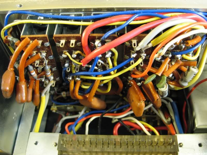
Looks like a tube amp under there. Very labor intensive manufacturing.
Yes, very labor intensive manufacturing. The Kenwood KA-6000 was pretty early (circa 1969) solid state. What can not be seen in the picture is the top side where several printed circuit boards are used for various circuit block functions.
 
In another thread there was a question about adjusting bias on the Kenwood KA-6000. I am posting my answer in this thread. It helps a lot if one has the manual however, with the schematic and these notes one should be able to make to proper adjustments.

There are three adjustments per channel on the amplifier driver board (aka MAIN AMP board). Potentiometers VR903/left channel and VR904/right channel adjust the “center voltage”. Potentiometers VR905/left channel and VR906/right channel adjust the bias.

When adjusting Bias Current, I follow this procedure:

The bias current for each channel should be set for 50mA as per the service manual.

1. With the amplifier turned off, measure emitter resistors R171, R172/left channel and R271, R272/right channel. Each resistor is specified as 0.47Ω, 2W, +/- 10%. Since they are relatively low value resistors, use a Kelvin connection to get an accurate reading. If they are out of specification, replace them. If they are in specification go to step two.

2. Adjust the left channel bias. Connect a sensitive voltmeter the across R172/left channel (Q7) output transistor’s emitter resistor. Turn on the amplifier and adjust VR905/left channel bias adjust trim potentiometer. There will be a 23.5mV voltage drop across the resistor when there is 50mA flowing through it, assuming that the resistor is exactly 0.47Ω.

3. Adjust the right channel bias. Connect a sensitive voltmeter the across R272/right channel (Q8) output transistor’s emitter resistor. Turn on the amplifier and adjust VR906/right channel bias adjust trim potentiometer. There will be a 23.5mV voltage drop across the resistor when there is 50mA flowing through it, assuming that the resistor is exactly 0.47Ω.

4. Since there may be some interaction between the two channels, check to see if the left channel bias is still correct or better yet; if you have two meters connect one to each of the two resistors when you make the adjustments.

When adjusting the Center Voltage, I follow this procedure:

1. With the amplifier turned off connect two 20kΩ resistors in series between the + and Ground terminals of the main B+ capacitor. The junction of the two resistors will establish the true midpoint of the supply once the amplifier is turned on. The 43V reading in the manual assumes that the B+ supply is 86V. The real B+ supply voltage will depend on the mains input voltage which can vary quite a bit.

2. Connect one lead of a floating (not referenced to ground) voltmeter to the junction of the two 20kΩ resistors. The other input to the voltmeter is then connected to the + terminal of the large left channel C171 output coupling capacitor. Turn the amplifier on and adjust VR903 (left channel center adjust trimmer) until the meter reads 0V. The left channel output is now centered. Turn the amplifier off and go to step 3.

3. Connect one lead of a floating (not referenced to ground) voltmeter to the junction of the two 20kΩ resistors. The other input to the voltmeter is then connected to the + terminal of the large right channel C271 output coupling capacitor. Turn the amplifier on and adjust VR904 (right channel center adjust trimmer) until the meter reads 0V. The right channel output is now centered. Turn the amplifier off and go to step 4.

4. Remove the two 20kΩ resistors.

VR901/left channel and VR902/right channel are for adjusting the protection circuits. To adjust the protection circuit the manual suggests:

1. connect 4Ω resistors to the speaker outputs.
2. inject a 1kHz. sine wave into the AUX input with all tone controls “flat”
3. increase the volume until one observes the waveforms are clipped when viewed on an oscilloscope.
4. adjust VR901 (VR902) until the waveforms “show fluctuation”.
5. “For the sake of good order, repeat lowering and increasing the input to make sure whether any fluctuation is noted in the waveforms before or after the clipping points with the contact load changed to 8 ohms. The waveforms on the oscilloscope should show iterative effect in case the terminals of the load are shortcircuited.”
 
Last edited:
I'm working on one of these and the big 4000uF 100V 63mm cap is about to run out.
I was curious if I could replace this with as much as 15,000uF?
I've increased the coupling caps from 3300uF to 10,000uF already.
 
I'm working on one of these and the big 4000uF 100V 63mm cap is about to run out.
I was curious if I could replace this with as much as 15,000uF?
I've increased the coupling caps from 3300uF to 10,000uF already.
Installing a larger main power supply capacitor will do several things. On the positive side, the larger capacitor should reduce power supply ripple and provide more reserve current during high power transients. On the negative side, peak inrush current will be greater as will the cycle by cycle charging current. Too high peak inrush current could cause the mains fuse to blow and/or damage the power transformer and/or bridge rectifier diodes. Whether or not you will see the negative effects with the 15,000µF you are proposing, I do not know. My experience would suggest that doubling the capacitance value should be safe.

Installing larger output coupling capacitors will extend the low frequency bandwidth capability of the amplifier. However, one should avoid stacking the low frequency poles at or near the same frequency or the amplifier may become unstable. Increasing the capacitance values of all the coupling capacitors, within the power amplifier feedback loop, by an equal percentage should result in low frequency stability consistent with the original design.
 
Installing a larger main power supply capacitor will do several things. On the positive side, the larger capacitor should reduce power supply ripple and provide more reserve current during high power transients. On the negative side, peak inrush current will be greater as will the cycle by cycle charging current. Too high peak inrush current could cause the mains fuse to blow and/or damage the power transformer and/or bridge rectifier diodes. Whether or not you will see the negative effects with the 15,000µF you are proposing, I do not know. My experience would suggest that doubling the capacitance value should be safe.

Installing larger output coupling capacitors will extend the low frequency bandwidth capability of the amplifier. However, one should avoid stacking the low frequency poles at or near the same frequency or the amplifier may become unstable. Increasing the capacitance values of all the coupling capacitors, within the power amplifier feedback loop, by an equal percentage should result in low frequency stability consistent with the original design.

So essentially tripling from 4,000 to 15,000 would be an issue?

Where are the other coupling caps? Would they be the three other, smaller clamped caps?
 
So essentially tripling from 4,000 to 15,000 would be an issue?
Not necessarily. It could be an issue. I have not tried tripling the capacitance value of the main power supply capacitor on a Kenwood KA-6000. If you install the 15,000µF capacitor in your Kenwood and it works out fine without any negative side effects, then you can post this as a worthwhile modification. My point in the earlier post was that there is not always a free lunch when installing larger capacitance value capacitors in a power supply.

Where are the other coupling caps? Would they be the three other, smaller clamped caps?
The other coupling and bypass capacitors in the amplifier feedback loop are:

C173, C273 located on the underside of the chassis.

C327, C328, C921, C922, C919, C920, C923, C924 all located on the MAIN AMP “UA1343K1” board.

The three smaller clamped capacitors are power supply capacitors.
 
Not necessarily. It could be an issue. I have not tried tripling the capacitance value of the main power supply capacitor on a Kenwood KA-6000. If you install the 15,000µF capacitor in your Kenwood and it works out fine without any negative side effects, then you can post this as a worthwhile modification. My point in the earlier post was that there is not always a free lunch when installing larger capacitance value capacitors in a power supply.

The other coupling and bypass capacitors in the amplifier feedback loop are:

C173, C273 located on the underside of the chassis.

C327, C328, C921, C922, C919, C920, C923, C924 all located on the MAIN AMP “UA1343K1” board.

The three smaller clamped capacitors are power supply capacitors.

Damn, I've already recapped the rest of it! How big of an issue is this?
 
I don't have the manual, just a schematic (scan of original Kenwood document). It shows the bias current to be 50mA, not 100mA (illustrated on diagram by an arrow labeled '50mA' inset in each supply rail from the 'test' plug to the output transistors Q5 and Q6. This corresponds to 23.5mV across each 0.47ohm resistor. 50mA seems more consistent with what I would expect for an early solid state amp. Does the manual clearly state 100mA?
BTW my scan came from here: http://www.fotoalbumet.com/homepage...0cac7d10460e296e21ef7c88&intDesign=1&intEdit=
which seems to be a little treasure trove of Kenwood circuits!

In another thread there was a question about adjusting bias on the Kenwood KA-6000. I am posting my answer in this thread. It helps a lot if one has the manual however, with the schematic and these notes one should be able to make to proper adjustments.

There are three adjustments per channel on the amplifier driver board (aka MAIN AMP board). Potentiometers VR903/left channel and VR904/right channel adjust the “center voltage”. Potentiometers VR905/left channel and VR906/right channel adjust the bias. The bias current for each channel should be set for 100mA.

VR901/left channel and VR902/right channel are for adjusting the protection circuits. To adjust the protection circuit the manual suggests:

1. connect 4Ω resistors to the speaker outputs.
2. inject a 1kHz. sine wave into the AUX input with all tone controls “flat”
3. increase the volume until one observes the waveforms are clipped when viewed on an oscilloscope.
4. adjust VR901 (VR902) until the waveforms “show fluctuation”.
5. “For the sake of good order, repeat lowering and increasing the input to make sure whether any fluctuation is noted in the waveforms before or after the clipping points with the contact load changed to 8 ohms. The waveforms on the oscilloscope should show iterative effect in case the terminals of the load are shortcircuited.”
 
I don't have the manual, just a schematic (scan of original Kenwood document). It shows the bias current to be 50mA, not 100mA (illustrated on diagram by an arrow labeled '50mA' inset in each supply rail from the 'test' plug to the output transistors Q5 and Q6. This corresponds to 23.5mV across each 0.47ohm resistor. 50mA seems more consistent with what I would expect for an early solid state amp. Does the manual clearly state 100mA?
Good catch. 50mA is the correct bias current per channel. I will go back an correct my earlier post. Thanks.
 
Hello
I realize this is a 2 year old plus thread but I must ask is there different versions of the KA-6000, I have one in front of me with original repair sch and manual and not a single number relates to my boards, No VR905 or VR906, the pictures are the same through out this topic here. Totally baffled. Thanks
 
I realize this is a 2 year old plus thread but I must ask is there different versions of the KA-6000, I have one in front of me with original repair sch and manual and not a single number relates to my boards, No VR905 or VR906, the pictures are the same through out this topic here. Totally baffled. Thanks
I have several schematics of the Kenwood KA-6000. The ones in my service manuals do not have © dates. The one included with my original KA-6000 shows © 1969-9 and another schematic shows a © 1971-1. Does your schematic have a ©?

Looking at the schematic; all the resistors on the MAIN AMP board start with the number R900. The actual labels on the printed circuit board drop the 900 prefix. e.g. Schematic VR901 becomes VR1 on the printed circuit board and resistor R901 schematic is R1 on the printed circuit board. So for schematic VR905 and VR906; look for VR5 and VR6 on the printed circuit board.

Picture of the MAIN AMP board:
replace2sc458.jpg
 
Hi, I know this is an old thread but does anyone know about replacing the 4000uf cap with the 15000uf cap? I noticed it mentioned and wondered if it caused any problems?
 
Back
Top Bottom