• The move to the new server is done. There are some software and database maintenance updates in process. This has us passing the hat around to help out. We appreciate any donations. Seriously, even a dollar helps. The payment page may be found here - https://www.audiokarma.org/support.html

Strange Stability Enhancement Trick

LinuxGuru

Well-Known Member
Hi !

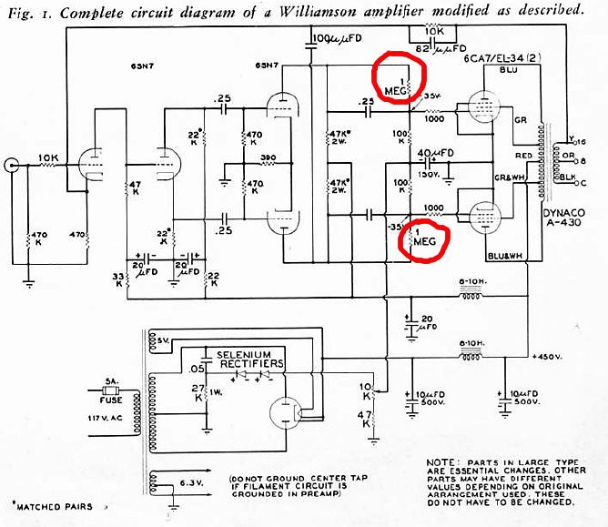
in the article published in Audiocraft by David Hafler, "Modernize your Williamson Amplifier", author introduced strange trick - connecting 1 MOhm resistors parallel to coupling caps leading to output stage. As Mr Hafler wrote, this was done for phase correction purposes in order to enhance stability of the amplifier.

Someone could explain if this technique really working, and if yes, how?

These resistors raise positive DC on the grids of output tubes, and if second 6SN7 fails (e.g. worn out cathode), is very likely to cause overheating of output tubes because of lowering BIAS voltage.

7178777796_3b8e5eaec1_b.jpg
 
Register to hide this ad
I can't comment on the phase shift because I don't know enough to evaluate that. With the high value resistors in there it looks like he could get the needed negative bias he needs on the grid. It looks to me like it would put slightly greater current and filtering demands on the power supply but not enough to matter very much. With modern solid state diodes that could be built very reliably today. Given the right selection of resistors, as long as the coupling caps and the resistors are both up to spec it should work OK. I would think however that with the RC parallel circuit in place, the owner should be a bit more then casual in monitoring the condition of those parts over a period of decades.

Just my thoughts on it. Strictly an amateur point of view on this subject.

Shelly_D
 
Damn, I thought I had seen all the "improved" Williamson circuits, but this one is new to me.

Paging one of the smart guys.
 
Speaking of neat tricks, the last Williamson I built used filament TXs backwards off the PT 6.3 to make 120v for each channel's bias supply construction.
 
Never seen a Williamson with fixed bias before. All the schematics I've run across were cathode bias with the balance pot.
 
It came from either the Acrosound TX catalog, or an older issue of Sound Practices. Pretty wild circuit, I'll see if I can dig it up.
 
Those resistors take effect below about 0.64Hz, so they're reducing phase shift in the deep subsonic region only. LF stability was a problem in Williamsons due to the stackup of three LF poles (including the OPT). I can easily imagine that shifting one of them could help settle it down. If you want a full technical understanding of this issue, then I recommend High Fidelity Circuit Design by Crowhurst & Cooper.
 
The technique works, and works very well as I can attest. Mike's comments of why the network is (sometimes) needed, is right on as usual. But from the standpoint of practical application, the general thought is this:

The amplifier employs a feedback level of 20 db, which was consistent with all the quality versions of the Williamson amplifiers that were produced. A 20 db feedback level means that the gain of the amplifier has been reduced by a factor of 10 by the NFB loop, as has the distortion level as well. Put another way, if the amplifier required 1.5 vac to drive it to full power output with the feedback loop connected, it would only take .15 vac to develop full power with the feedback loop disconnected.

Now, look carefully at the coupling network in question. Notice that the "strange" resistor is 1 meg, while the output tube grid resistor is 100K. This means that at the very lowest frequencies -- those below which the .25 uF cap alone can effectively couple -- the amplifier is now basically direct coupled at this coupling point, and effectively removes one of the LF poles from the circuit that Mike mentioned above. And, with a 10:1 reduction ratio in this network, it has effectively canceled out the 10X reduction of the NFB loop as well. As a result, this technique then has the capability of producing a very high degree of LF stability in a NFB amplifier, that would otherwise be quite unstable if only capacitive coupling were used at the coupling point in question.

Yes, it will require slightly more out of the bias supply to compensate for the DC that is coupled through the 1 Meg resistors to the output stage, but this is hardly a significant problem compared to the problem that is solved.

This is just one more example of how Hafler/Laurent were at the top of the game when it came to producing highly stable feedback amplifiers. At a time in the hifi world when most Williamson designs were so famous (or is it infamous?) for burning out tweeters and causing woofers to "breathe" with no signal applied (due to all manner of instabilities), Hafler designs simply worked, and worked very well with impeccable manners.

I hope this helps!

Dave
 
Thanks to all who replied!

I wonder is it possible to use this technique with LTP + PP, as shown on the schematic attached (circled red)? I'm not sure LTP with DC coupling to the output stage (albeit with 1 MOhm resistors) is a good thing.

There is another cap in question left from original schematic (circled green), which have no effect on oscillation.

7181072064_b7279a829c_b.jpg
 
Yep. As Dave mentioned, this is just "cancelling out" a LF rolloff. That, in a four-stage amp like a Williamson, can make the difference between having a stable amp or a LF oscillator.

Other manufacturers tackled this problem in other ways- if you ever wondered why a Heathkit W5 amp has a 1uf (one microfarad) cap as a coupling cap to the output tubes- this is it. Heathkit chose to drop the rolloff frequency of the last coupling by two octaves, compared to what's used here- that was also enough to space out the critical phase shift points, to where the amp became stable...

Regards,
Gordon.
 
Absolutely right Gordon. If this shows anything, it shows why indiscriminately changing coupling cap values is not necessarily a good thing. All the good you think you may be doing may in fact be canceled out by other problems you are creating. Anytime the RC coupling circuits of a NFB amplifier are altered -- or any of the time constant elements of the circuit are altered for that matter -- the low and high frequency stability of the amplifier must be thoroughly checked to make sure it has appropriate manners under all possible loading conditions.

Dave
 
Every day I learn something new on this site. I read just about every post I see when "certain" people post a comment. Not to beat a dead horse, that was done quite well already, but this is why comments and recommendation are so appreciated on this site.
 
Linuxguru- that cap you have circled in green- I'd have to see where someone did an overload analysis of the amp to know for sure, but I'd guess that cap possibly has some effect in overload-recovery of the amp (helping deal with momentary bias shift due to driving the amp overly deep into the 'B' part of Class AB).

Either that, or it's a gain-tweaking mechanism for just that "side" of the PP pair, given its placement in a cathode feedback loop. Could just have given better overall AC balance between the two sides?

Regards,
Gordon.
 
Gordon -- I've seen that cathode trick cap before -- primarily in the Fisher 70/80/100AZ series of amplifiers that also uses a PP CFB winding from the OPT -- although it's not connected exactly the same way as shown in Linux's schematic. My take on it was that it was likely compensating for the geometry of the winding in the OPT (causing different winding capacitances on each side), and so the external cap was only required on one side of the winding.

I never really investigated the effects of the cap beyond those thoughts, but that was my take on it anyway.

Dave
 
Every day I learn something new on this site. I read just about every post I see when "certain" people post a comment. Not to beat a dead horse, that was done quite well already, but this is why comments and recommendation are so appreciated on this site.

200% agree. Collective knowledge and brainstorming often is the best way to deal with stubborn problems.
 
Gordon -- I've seen that cathode trick cap before -- primarily in the Fisher 70/80/100AZ series of amplifiers that also uses a PP CFB winding from the OPT -- although it's not connected exactly the same way as shown in Linux's schematic. My take on it was that it was likely compensating for the geometry of the winding in the OPT (causing different winding capacitances on each side), and so the external cap was only required on one side of the winding.

I never really investigated the effects of the cap beyond those thoughts, but that was my take on it anyway.

Dave

Speaking of the winding geometry, does anyone know of an output TX with the same DCR on each side of the CT? I think it's Morgan Jones that speaks of high quality OPTs that do, but I've yet to see any. I understand about using a longer wire to get the same number of turns, but how can this be avoided? Winding recipes boggle my mind.
 
This means that at the very lowest frequencies -- those below which the .25 uF cap alone can effectively couple -- the amplifier is now basically direct coupled at this coupling point, and effectively removes one of the LF poles from the circuit that Mike mentioned above. And, with a 10:1 reduction ratio in this network, it has effectively canceled out the 10X reduction of the NFB loop as well. As a result, this technique then has the capability of producing a very high degree of LF stability in a NFB amplifier, that would otherwise be quite unstable if only capacitive coupling were used at the coupling point in question.

Yes, it will require slightly more out of the bias supply to compensate for the DC that is coupled through the 1 Meg resistors to the output stage, but this is hardly a significant problem compared to the problem that is solved.

Hi, dcgillespie! Is there any other similar tricks? Actually I'm having problems not with Williamson, but with 2nd schematic which seem to be in need for total reworking. Small HF oscillation (about 8 - 20 mV) on output, at 30 - 60KHz, and LF oscillation, at around 1 - 2 Hz. I tried to suppress HF oscillation with RC networks shown in dark-red without any success.
I suspect this could be due high capacitance between output transformer primary and secondary windings - about 5nF, or long HV wires lying around table.
Leakage inductance is 9 mH for one model and 18 mH for another. so this should not be an issue.
I tried to replace LTP tubes (6N6P) with 12BH7 and 6SN7, adding screen stoppers with no success. With the oscilloscope check I found source of HF oscillation is LTP.
 
Speaking of the winding geometry, does anyone know of an output TX with the same DCR on each side of the CT? I think it's Morgan Jones that speaks of high quality OPTs that do, but I've yet to see any. I understand about using a longer wire to get the same number of turns, but how can this be avoided? Winding recipes boggle my mind.

Small DCR difference between 2 halves of primary should not be source of concern.
If you want almost identical DCR, you need split bobbin into 2 identical section.
One of my transformers for example have 35.3 and 41.1 Ohms.

Compared to total primary impedance 3.3 KOhm this is close to nothing.
 
Linux -- If I recall correctly, you've been battling this one for a while now.

I think the first approach (which you've likely already done) is to disconnect the global NFB network -- but leave it disconnected. That way, you know you are not dealing with any stability issues related to the feedback network. With the network disconnected, then:

1. Any HF instability must be individual stage or layout related. With the GNFB loop disconnected, there are simply no other possibilities that exist. If the unit still has HF instability in the LTP with the loop broken -- even with well proven tubes such as the 12BH7 installed in that position, then the only real option left is a layout fault. If the tube and feedback network possibilities are eliminated from a design that is otherwise quite conventional and well proven to be stable, then layout must be considered as a prime suspect.

2. If any LF instability issues remain, then the power supply decoupling networks must be suspect. Layout will usually have little effect on low frequency stability issues, but power supply decoupling can surely play a major role.

The goal is to get the amplifier completely stable with the GNFB loop open. If that is not achieved, it will surely not be stable with the loop closed, as that will tend to only aggravate the pre-existing stability issues already in place.

To troubleshoot the long tail pair, remove the output tubes (watching no load power supply voltages as appropriate -- use a variac if necessary) and the input stage tube, and replace the input stage tube with an appropriate resistor (from plate to cathode connections) to bias the LTP to the same operating point as if the input stage tube were actually in place. In this condition, the LTP is totally isolated by itself with no active stages either before or after it. It should now be a relatively simple task to trace down any HF instability that is originating from this stage.

To track down LF instability, the output stage will need to be fully operational. If LF instability is still in play with all tubes installed but the GNFB loop disconnected, then (again) replace the input tube with the same resistor as used to replace it with the HF stability work, and see if the LF instability stabilizes at that point. If so, then the power supply decoupling is suspect between the input and LTP stages.

In this manner you can trace down any instability issues that are basic to the amplifier proper before the loop is connected. With the amplifier stable in an open loop condition, then if any new stability problems crop up with the loop closed, you can deal with them then with the absolute knowledge that they are in fact loop related. Until you create this condition however, you don't really know what you're dealing with.

When you get the point where the amplifier is completely stable open loop, then, if LF issues become present (possibly again) when the loop is closed, then coupling techniques such as Hafler used might come into play, but you won't know that until the amplifier is made absolutely stable before the loop is closed.

I hope this helps. Good luck with it, and keep us posted!

Dave
 
Linux -- If I recall correctly, you've been battling this one for a while now.

Yes, Dave, and I'm ready to trash it and start building another one from scratch.
The only things I'm regret is a lost time and PCB which cost me a money.

I think I will get rid of DC coupled LTP and will use AC coupled one based on 6SN76N8S/6CG7.
Due to the DC coupling original LTP have non-optimal BIAS point and high THD at high signal amplitude (original design evaluated by Radio Gijutsu have sharp increase of THD at 10 KHz / power > 30W ). I suspect LTP and phase shift by output transformer (at these frequencies) as a cause of this.
 
Back
Top Bottom