

You are using an out of date browser. It may not display this or other websites correctly.
You should upgrade or use an alternative browser.
You should upgrade or use an alternative browser.
Zilch's AK Design Collaborative - Econowave Speaker
- Thread starter Zilch
- Start date

jackgiff
Well-Known Member
This is maybe better
Here is the FR's for the standard E'Wave crossover with values of 15 uF for C2, 1.1 mH for L1, 3 uF for C1, and no capacitor installed for C3. Transition across the crossover band is done with no bump. Doesn't even need a HF compensation capacitor.
This combo of DE250 and QSC waveguide/horn is driving me nuts. Microphone placement is extremely critical. Even the B&C woofer seems strange. Maybe they need metric values rather than English. Or I need to learn to speak Italian.
The response of the DC300 woofer is what sent me back to the B&C woofer. It may be that the cabinet is just not tuned for the Dayton (50 Hz), but the B&C just seems to perform better in this situation.
Here is the FR's for the standard E'Wave crossover with values of 15 uF for C2, 1.1 mH for L1, 3 uF for C1, and no capacitor installed for C3. Transition across the crossover band is done with no bump. Doesn't even need a HF compensation capacitor.
This combo of DE250 and QSC waveguide/horn is driving me nuts. Microphone placement is extremely critical. Even the B&C woofer seems strange. Maybe they need metric values rather than English. Or I need to learn to speak Italian.
The response of the DC300 woofer is what sent me back to the B&C woofer. It may be that the cabinet is just not tuned for the Dayton (50 Hz), but the B&C just seems to perform better in this situation.
Attachments


Russellc
Addicted Member
Didn't mean to slight the new stuff, I am just in a VERY cost consciencious mode now. The original is SUCH a GREAT DEAL. And of course the performance is amazing.
AMEN to that!:thmbsp:
russellc
Russellc
Addicted Member
I built my first set of ewaves with a derelict pair of Advents and $80 worth of parts thanks to group buys and parts on hand. The next set were better because I upgraded to D220Tis. Maybe veneered cabinets made them sound better as well. I'm looking forward to trying the next upgrade when the QSC WGs arrive. Probably in Valencia cabs first with the Dayton Classic 15" woofers. Maybe we'll have a set sorted out for the next AK Fest. I'm curious about modding a set of PH612 to take bolt-on drivers directly but I have only 1 set of PH612 on hand. If I order from PE soon I'll get another pair to hack up.
Hacking one up interests me as well. Hopefully it wont mess with the throat function like the bolt on to screw on adapters did. ( JBL waveguide and DE 250)
only one way to find out, chop 'er up!
Russellc
Russellc
Addicted Member
If I remember correctly those were the woofers I was going to originally use in my Barzilay cabinets. I ended up buying some 2213H's from Russell for that project. I couldn't pass up the deal he gave me. I think I have way too many projects around here. I'm going broke.
That's why I bailed on the 2213H project, beautiful pair with excellent condition
fairly new cones. I just have too many projects, Counterpoint pre, Mcintosh MR 67, Mcintosh MC 225, a measuring setup needs finished, and now I went and dived into a Pass F-5 project! (Plus the on going E'wave saga...):sigh:
russellc

Yes, and we can see why in Brandon's No Quarter verticals -- the nulls impinge -6 dB upon the on-axis response at +/- 10°. We don't have to be very far off the vertical center of the forward lobe before they affect the measured response in the crossover region. It was maddening at first for both Skywave and me; we've got to be smack on the forward axis for reliable measurements. The forward vertical lobe does not have a flat face....This combo of DE250 and QSC waveguide/horn is driving me nuts. Microphone placement is extremely critical.


Wayne Parham
Active Member
Yes, and we can see why in Brandon's No Quarter verticals -- the nulls impinge -6 dB upon the on-axis response at +/- 10°. We don't have to be very far off the vertical center of the forward lobe before they affect the measured response in the crossover region. It was maddening at first for both Skywave and me; we've got to be smack on the forward axis for reliable measurements. The forward vertical lobe does not have a flat face....
Now you see exactly what I was talking about when I said the vertical nulls in some of those speakers were so troublesome. It's why I have been so vocally adamant against round horns for the past decade or so, ever since first participating on audio messageboards. I took a lot of bashing over at Audio Asylum ten years ago from the tractrix guys because of my position. I took some heat for it again a couple years ago over at DIYaudio from the new kids on the block, the OS camp. I'm not sure what those guys are missing, but from where I'm standing, that teeny-tiny thin vertical strata (too thin for me to even call a forward lobe) is simply not useful. You just can't sit anywhere that you're not in a null. And who needs the tall vertical pattern at HF, that does nothing but cause ceiling slap.
Back when the tractrix guys used to preach their round horn mantra, at least I could shrug my shoulders thinking them straight-on-axis, head-in-a-vice guys. Some people like that, because it makes a sort of mysterious phasey quality. They like to talk about how it "clicks into focus" when they sit in the sweet spot. So for me to talk about uniform directivity with them was a paradigm shift they weren't willing to explore. They didn't care about constant directivity, so my passion for a uniform reverberent field just wasn't important to them. So be it.
But to me, the greater sin, if you can forgive my using a somewhat dramatic allegory, is when the new religion of "waveguides" came onto the scene bringing with them (gasp) round horns. I couldn't believe it. I mean, the horizontals are better when the tweeter is a radial, conical, quadratic or OS horn than if it's purely exponential or tractrix but if the horn (or "waveguide") is round, then the verticals are prohibitively narrow. What's the point of constant directivity if you have to be precisely on-axis in the vertical? That sort of defeats the point, in my opinion. You all saw the "debate" brought by the proponents of round waveguides, they went so far as to joke about how they don't listen on the floor and what not. I replied then that I considered that position to be irresponsible and unscientific, and I still do.
This also applies to any horn that is too tall in the vertical dimension. The extra mouth area helps give the horn better control by itself, which is a good thing. But when used in a loudspeaker system, the nulls can't be set far enough apart to be useful, so the horn's pattern control becomes meaningless. We all know that having the taller vertical height improves the horn's vertical control but it does so at the expense of a narrower forward lobe and too-closely spaced vertical nulls.
A compromise is the only reasonable solution, one that allows some loss in vertical pattern control in order to place the nulls far enough outside to be useful. As I've said for years and will say again, the goal, in my opinion, is to allow the nulls to sort of punctuate the pattern at the low end. But no matter what, you just can't let the vertical nulls be so close to the forward axis that they actually shrink the forward lobe to practically zero. This is the antithesis of constant directivity and no design should ever allow the nulls to be closer than 20° of the forward axis, in my opinion. Any speaker that cannot achieve at least a 40° arc between vertical nulls is just not good enough, if you asked me.
I think now you guys here are seeing more and more, hands on. Pretty interesting stuff isn't it? This is the kind of thing that separates average speakers from really great ones.
I've tried a LOT of configurations, and I've always sort of come back to 12" and 15" midwoofers with good cone damping and 90° horns with smooth features, uniform pattern in the horizontal and vertical dimensions that provide a smooth transition. I'm not necessarily looking for control all the way down in the vertical. We need it in the horizontal, but in the vertical, I'll trade some height for some pattern control. It can't be as thin as a Smith, but it can't be as tall as a round horn either. There are lots of shapes that will work, but just as many that won't.
Last edited:

Bauhausler
Rational Subjectivist
Here is the FR's for the standard E'Wave crossover with values of 15 uF for C2, 1.1 mH for L1, 3 uF for C1, and no capacitor installed for C3. Transition across the crossover band is done with no bump. Doesn't even need a HF compensation capacitor.
This combo of DE250 and QSC waveguide/horn is driving me nuts. Microphone placement is extremely critical. Even the B&C woofer seems strange. Maybe they need metric values rather than English. Or I need to learn to speak Italian.
The response of the DC300 woofer is what sent me back to the B&C woofer. It may be that the cabinet is just not tuned for the Dayton (50 Hz), but the B&C just seems to perform better in this situation.
The crossover he's referring to:
Bauhausler
Rational Subjectivist
Forward lobe width
I did the calcs for the QSC waveguide edge to edge with a 12" woofer and it came out to 40 degrees with a crossover frequency of 1800 hz. The crossover frequency of 1600 hz that we're using will push the nulls slightly outside that range.
For those confused by the above, increasing the distance between the driver centers (using a larger woofer or placing the woofer and waveguide farther apart) reduces the height of the forward lobe. A higher crossover frequency also reduces the height of the lobe.
I did the calcs for the QSC waveguide edge to edge with a 12" woofer and it came out to 40 degrees with a crossover frequency of 1800 hz. The crossover frequency of 1600 hz that we're using will push the nulls slightly outside that range.
For those confused by the above, increasing the distance between the driver centers (using a larger woofer or placing the woofer and waveguide farther apart) reduces the height of the forward lobe. A higher crossover frequency also reduces the height of the lobe.
WIRED OLAU Vertical Polars:
Center-to-center distance between drivers = 12".
Crossovers are eWave standard <95 dB.
These measurements reference waveguide axis @44" mic distance.
Forward lobe is 36° tall, centered ~9" below waveguide axis.
Upper null at top edge of cabinet at this distance, lower is 4" below the bottom edge.
Optimum L-pad attenuation 10:00 - 11:00 in ZilchLab; measurements taken @12:00.


Center-to-center distance between drivers = 12".
Crossovers are eWave standard <95 dB.
These measurements reference waveguide axis @44" mic distance.
Forward lobe is 36° tall, centered ~9" below waveguide axis.
Upper null at top edge of cabinet at this distance, lower is 4" below the bottom edge.
Optimum L-pad attenuation 10:00 - 11:00 in ZilchLab; measurements taken @12:00.
Attachments


Last edited:


skywave-rider
Slumming in Akihabara
Center-to-center distance between drivers = 12".
Crossovers are eWave standard <95 dB.
These measurements reference waveguide axis @44" mic distance.
Forward lobe is 36° tall, centered ~9" below waveguide axis.
Upper null at top edge of cabinet at this distance, lower is 4" below the bottom edge.
Optimum L-pad attenuation 10:00 - 11:00 in ZilchLab; measurements taken @12:00.
So for the OLAU EWave conversion, best approach is to tilt the speaker back or raise stands so as head is at woofer height, approx.
Polars look smooth at various angles, esp. up.
The null is amazing. Tell me that's not audible....

Why are u now using 44"?
Better summation?

Steve O2
Active Member
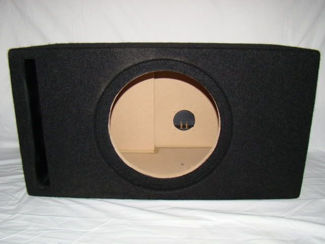
Im thinking of trying some of these with a pair of spare Cerwin Vega 12" woofers I have. The cabinets are almost the same dimensions as a CV 12"
The slot port intrigues me:scratch2:
Looks like there's enough room for the waveguide
http://cgi.ebay.com/12-ALPINE-TYPE-...emQQptZLH_DefaultDomain_0?hash=item45eeb85695


Hmnn...
The slot port intrigues me:scratch2:
Looks like there's enough room for the waveguide
http://cgi.ebay.com/12-ALPINE-TYPE-...emQQptZLH_DefaultDomain_0?hash=item45eeb85695
Hmnn...
Bauhausler
Rational Subjectivist
So for the OLAU EWave conversion, best approach is to tilt the speaker back or raise stands so as head is at woofer height, approx.
Polars look smooth at various angles, esp. up.
The null is amazing. Tell me that's not audible....
Why are u now using 44"?
Better summation?
I ran mine (Advent cabs and woofers, PH612/D220Ti) on 12" stands with significant tiltback. That's what my ears told me sounded best.
I measured a pair of OLAU cabs and the total width is just over 14". The baffle is too narrow for the QSC WG. BUT... if a sub-baffle was added above the woofer hole filling the upper portion of the cabinet to allow the QSC WG to be mounted with its rim overlapping the edge of the cabinet the WG would be significantly forward of the woofer and could be edge-to-edge with it. The sub-baffle would also cover the original tweeter hole. It doesn't look difficult and would have advantages. It would mitigate some of the excess depth of the QSC WG/DE250 combo, improving phase relationships by over an inch. If made removable, the sub-baffle could actually overlap the very thin rim of the woofer, further improving c-to-c distance.
Before doing another set of ewaves in ULA cabs I think I'd have to work out some damping and stiffening measures tha tdidn't steal too much internal space. The cab could definitely be stiffer and the bass would benefit from resonances being reduced. Maybe some metal bracketry and rods that could be tensioned a la Michael Green.
But that will have to wait until the QSC waveguides arrive in a month.
***EDIT***
The rim depth of the OLAU cabinet is a shade over 1", which is a useful amount of horizontal displacement to gain versus surface mounting both the woofer and the WG. The vertical height from the edge of the woofer hole to the top of the baffle is 10.75". This means that the QSC WG would almost completely fill the upper baffle space vertically. Now if the WG's baffle cutout was big enough to allow the woofer to be passed through and back mounted in its original hole (with roundover on teh front edge) then another .75" of displacement could be gained. But I don't think it's necessary for the WG cutout to be that wide if the WG is mounted 1" forward of the original baffle.
Last edited:


skywave-rider
Slumming in Akihabara
...
I measured a pair of OLAU cabs and the total width is just over 14". The baffle is too narrow for the QSC WG. BUT... if a sub-baffle was added above the woofer hole filling the upper portion of the cabinet to allow the QSC WG to be mounted with its rim overlapping the edge of the cabinet the WG would be significantly forward of the woofer and could be edge-to-edge with it. The sub-baffle would also cover the original tweeter hole. It doesn't look difficult and would have advantages. It would mitigate some of the excess depth of the QSC WG/DE250 combo, improving phase relationships by over an inch. If made removable, the sub-baffle could actually overlap the very thin rim of the woofer, further improving c-to-c distance....
Go for it.
I suppose the sub baffle could be made in any shape.
It would heighten the forward lobe, just guessing, to 50° or so, by pushing the nulls further apart. I'll be converting a a pair of NLAs soon, in which the woofer is higher up; it'll be interesting to see the difference.Thnx Much!!
How much would repositioning the WG ajacent to the woof affect the measurements IYE?
Anywhere between the driver centers is fine, between red and black.So for the OLAU EWave conversion, best approach is to tilt the speaker back or raise stands so as head is at woofer height, approx.
The lower null is similar, at -24". Wayne and Jack both got similar results using different designs. See Fig. 1 here:The null is amazing. Tell me that's not audible....
http://www.rane.com/note160.html
The test stands and mic location haven't moved, so it's just a matter of where stuff ends up within a couple of inches. If I "reorganized," there'd be more room, but then I'd have to make decisions.Why are u now using 44"?
Better summation?

Looks like a "Yes." Confirm that the 12" x 6.5" standard eWaveguide will fit there.Dead tweeter. E-Wave candidate?
Jensen era Advent Legacy I
It's more difficult to find 15" drivers that play competently up to 1.5 kHz, the directivity is not as well matched, and the center-to-center distance is of necessity greater. None of that's a deal breaker, but 10s and 12s are a better match and easier to work with.... :yes:Everyone is running 12's, what about 15's?
Last edited:
Here are my Econowaves
Hi folks,
Here are my Econowaves. Crossover used the Zilch pcbs. D220ti / DC300 combo in Realistic Mach One cabs. I'm very pleased with the sound. I will probably built a retro style pair for my oldest son in a trap cab, similar to the ones Jack showed.
Thanks to everyone for the input to the build.
Hi folks,
Here are my Econowaves. Crossover used the Zilch pcbs. D220ti / DC300 combo in Realistic Mach One cabs. I'm very pleased with the sound. I will probably built a retro style pair for my oldest son in a trap cab, similar to the ones Jack showed.
Thanks to everyone for the input to the build.
Attachments


Rhubarb
a spinnin' an' a grinnin'
I *think* that the Advent Legacy is a 6 ohm speaker...not too sure though. I do know that it is only a 10" woofer.
Should be plenty enough mounting space for an eWaveguide, is 8" enough depth? Should be, since the driver and the horn would only be about 6.2" deep.
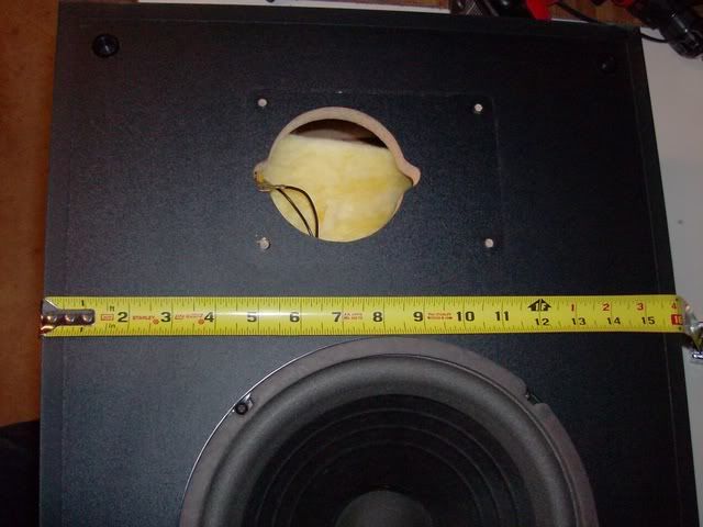
Just thinking...looks like a lot of fun! My AS-2Bs might be a better match...
Should be plenty enough mounting space for an eWaveguide, is 8" enough depth? Should be, since the driver and the horn would only be about 6.2" deep.
Just thinking...looks like a lot of fun! My AS-2Bs might be a better match...