• The move to the new server is done. There are some software and database maintenance updates in process. This has us passing the hat around to help out. We appreciate any donations. Seriously, even a dollar helps. The payment page may be found here - https://www.audiokarma.org/support.html

Leak amp refurb - burned component?

BmWr75

Top octave? pfffffftttttt
Subscriber
Leak Point One Stereo preamp and Stereo 20 amp refurb

Hey Guys,

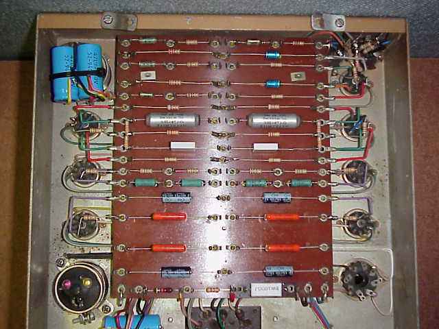
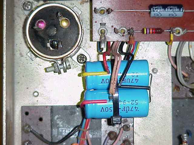
I started helping @markshan with the refurb on the Leak tuner/pre/amp he scored recently. Here are a couple of pictures of the component board in the amp. There is a burned component on the lower right of the board, appears it also cooked a green capacitor right next to it.

Anyone know what the burned component might be and have a hypothesis on why it may have fried? I'm guessing a sand cast type resistor, if I recall the term correctly. @markshan has a schematic for the amp, but I've not seen it yet.

Anyone know which of the 4 caps are the coupling caps? I can figure this out when I get a copy of the schematic, but am just guessing for now.

Might the four green 50uF caps be newer than all the other metal can caps?

Thanks,
Scott

EDIT1 - found this post in @markshan thread: http://www.audiokarma.org/forums/showpost.php?p=5513986&postcount=112

EDIT2 - found the schematic here: http://www.audiokarma.org/forums/showpost.php?p=5495370&postcount=29

EDIT3 - tested all the Mullard tubes. They all test strong. As do the four EF86 preamp tubes.


attachment.php
 
Last edited:
Register to hide this ad
The burned green resistor is R21 on the schematic -- a 100 ohm resistor between the rectifier and the output stage B+ source. It will run very warm normally, but could easily be stressed much hotter from a shorting filter cap, or an output stage drawing too much current.

The burned green cap next to it is one of the cathode bypass caps in one of the output stages.

Besides replacing those two components, the unit should have its power supply and coupling caps replaced at a minimum before powering it up again.

Good luck with your amp!

Dave
 
The burned green resistor is R21 on the schematic -- a 100 ohm resistor between the rectifier and the output stage B+ source. It will run very warm normally, but could easily be stressed much hotter from a shorting filter cap, or an output stage drawing too much current.

The burned green cap next to it is one of the cathode bypass caps in one of the output stages.

Besides replacing those two components, the unit should have its power supply and coupling caps replaced at a minimum before powering it up again.

Good luck with your amp!

Dave

Thanks Dave. Check my understanding on these cap #s:

Power supply = C10, C11, C12, C13

Coupling caps = C4 R, C6 R, C4 L, C6 L

Cathode bypass = C7 R, C8 R, C7 L, C8 L

Would this amp benefit from some Russian PIO coupling caps? Or, what coupling caps would you recommend?

I usually just use Orange Drops for the small uF caps and Sprague Atoms for the large uF caps. Probably will just disconnect the gold power supply multi-cap cans and leave them in place for looks, and install the new individual PS caps under the chassis.
 
Last edited:
75 -- Don't forget about C3 R&L, as these are coupling caps as well. You will also want to replace C2 R&L, and C5 R&L, which are bypass caps in the audio path. Otherwise, you've got it down perfectly.

As for types of components, that is largely a personal preference, with each having their own tastes. I do know that many favor the PIO caps for coupling positions in vintage equipment.

Dave
 
Scott, here are the links I mentioned finding info on that component...

One safety feature incorporated is the use of a 100ohm/1W resistor that overheats and de-solders itself from the circuit board when overloaded. This is a simple, utilitarian, but effective, method of protecting the power supply when excessive current is drawn.

If a coupling capacitor fails and puts a positive voltage onto the control grid of the output valve, it will pass more current and may eventually go virtual short circuit. The resistor will then get extremely hot, and, if fitted correctly, will de-solder itself from the board, thus protecting the mains transformer from damage.

I also read somewhere about not wrapping this resistor to the post, but just soldering it to the outer edge so that it wil drop when it gets hot. I can't find that link now.

Here are pictures I found of how to deal with those two big caps. Solution A is to replace them and let the new ones show. I don't much care for this from an ascetic viewpoint.

6795001083_551699cf8e_o.jpg


Here are the new ones wiretied underneath and the old ones left in place to keep the vintage appearance. I much prefer this.

pcb2.jpg


pcb3.jpg
 
might I comment that that is one gorgeous layout underneath. I love tagboard construction, its so clean looking.
 
might I comment that that is one gorgeous layout underneath. I love tagboard construction, its so clean looking.

Tis why I like the design of the leak, that board layout is where it's at. The next scratch amp I plan on building will be laid out with a board just like that.
 
Mark,

We will go with the 32uF caps under the chassis and leave the gold originals in place.

Don't order any caps yet, I'm still thinking about which ones we might use PIO (paper in oil) caps as replacements.

I'll email you a final list of caps and resistors to order in a day or two.

Scott
 
I'm not ordering anything until you tell me to.

Except that I may try to find the color match paint on my own. I don't think I can screw that up too bad.
 
I want a LEAK amp so bad it isn't even funny. Never even saw one though. Some day.:yes:

My wife sold hers back in the early '90s before I had a clue, she even offered them to me.:tears: I wanna jump off a bridge when I think about it...
 
Scott: I have a pair of Leak TL/25+ amps. I had the caps restuffed and you can't tell. I'm still thinking about the best way to make an RCA-input-jack-to-8-pin-tube-socket adapter . . .
 
BuzzK: I'm going to mount pairs of 32 uF PS caps underneath the chassis instead of restuffing the cans. Will look like this.

attachment.php
 
Last edited:
Resistor question

The schematic calls for R21 to be a 100 ohm 3 watt. This is the resistor that protects the amp from pulling too much voltage, it did it's job in this amp already.

Can I use a 100 ohm, 5 watt instead? That is all Antique Electronic Supply has, but they do have all the right caps for the amp.
 
Last edited:
Back
Top Bottom