

You are using an out of date browser. It may not display this or other websites correctly.
You should upgrade or use an alternative browser.
You should upgrade or use an alternative browser.
RSIIIA Crossover assistance please.
- Thread starter INeedInfo
- Start date
I just put in the orders now. I'm a little slow ")
It may be a litte tight in there and I hope I didn't screw this up. I tried to stay as close to the specs as I could. I ordered:
Parts Express
6 x 400uF 100V Electrolytic Non-Polarized Crossover Capacitors
4 x 8.0uF 100V Electrolytic Non-Polarized Crossover Capacitors
2 x 6.8uF 100V Electrolytic Non-Polarized Crossover Capacitors
Madisound:
8 x Carli MET 4.7 mfd Non-Polar Mylar Capacitor 150V
2 x Carli MET 6.8 mfd Non-Polar Mylar Capacitor 150V
And now that I've typed this all out and am looking at it, it's going to be pretty busy in there but hopefully will fit
Well, alrighty then. I finally got the capacitors and installed in one speaker and it sounds terrible. Not sure what I did wrong, but I definitely did it wrong.
I went over it and made sure I installed in same places/order as the ones I had removed. I checked the other speaker to be sure and it looked ok.
Does anyone see anything wrong with the capacitors I ordered?
Non-polar means it doesn't matter what direction they go in, is that correct? These don't need a break in do they?
Hmmm.
I'm going to get some sleep and take another listen. If I'm still having an issue I guess I'll just put the old ones back in for now.
Define sounds horrible. The entire audible spectrum, more midrange, more on the high side, more on the lows. You may only have some high resistance solder connections.
One thing I would be leery of is those large value 400uf non polar 'lytics you got, on the large value keep the originals unless you know for a fact they have gone way south. I've had bunches of high uf value (200uf+)Bennic, Erse, and I forget what was printend on the other ones I tried. From madisound, parts express and erse. They all are about as usefull as thousand year old elephant dung. The 150's and below were more consistent, but anything over that was crazy bad. ESR all over the place, going as high as .05 , and that is at the high freq my meter uses, not at the lower frequencies the high value non polars see in the crossover. At those frequencies it would be much much much worse. The capacatance of them was also all over the place, pretty damn random as far off as +/- 30 percent. One "bad" original 150uf cap in my rs 4.5's caused a 5db drop out in the mids and a much duller sound, it's capacitance was fine, my meter showed it's ESR at .04 when all the other original lytics in the crossover showed .02. It took me 25 Bennic 150's to find consistent ones to use to replace the 6 150's and two 300's between the pair of speakers. I ordered that many since they were cheap and I already had reason to suspect horrific quality control on them from other comments I read, I literally ended up with 2 that I didn't use that were ok, the rest in the garbage.
One thing I would be leery of is those large value 400uf non polar 'lytics you got, on the large value keep the originals unless you know for a fact they have gone way south. I've had bunches of high uf value (200uf+)Bennic, Erse, and I forget what was printend on the other ones I tried. From madisound, parts express and erse. They all are about as usefull as thousand year old elephant dung. The 150's and below were more consistent, but anything over that was crazy bad. ESR all over the place, going as high as .05 , and that is at the high freq my meter uses, not at the lower frequencies the high value non polars see in the crossover. At those frequencies it would be much much much worse. The capacatance of them was also all over the place, pretty damn random as far off as +/- 30 percent. One "bad" original 150uf cap in my rs 4.5's caused a 5db drop out in the mids and a much duller sound, it's capacitance was fine, my meter showed it's ESR at .04 when all the other original lytics in the crossover showed .02. It took me 25 Bennic 150's to find consistent ones to use to replace the 6 150's and two 300's between the pair of speakers. I ordered that many since they were cheap and I already had reason to suspect horrific quality control on them from other comments I read, I literally ended up with 2 that I didn't use that were ok, the rest in the garbage.
Thank you everyone for taking the time to look at this and comment. This forum has been great.
I think my 400uf's were around 430, I checked them all. The 600uf's I pulled out were around 700uf, go figure.
It's hard to explain, but it seems like the bass volume/intensity is way down and the lower mid-range is weak. When I turn it up bass/lows aren't crisp or sharp.
The emits/tweeter is amazing though, like crystal
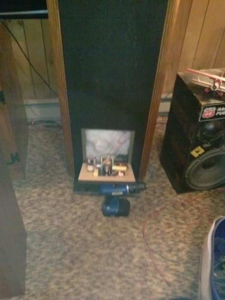
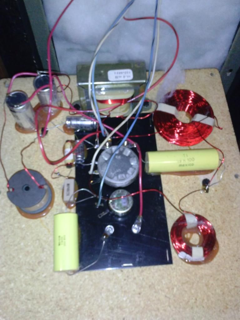
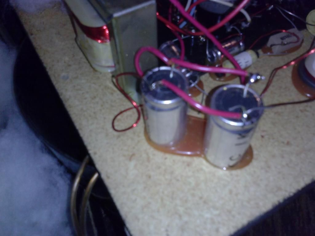
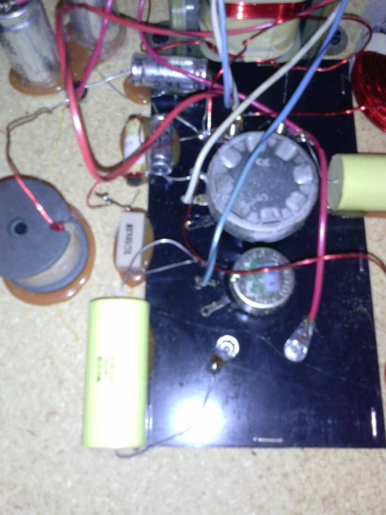
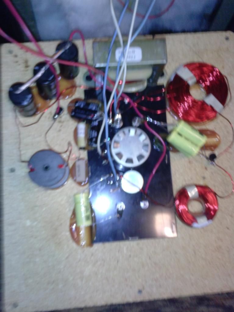
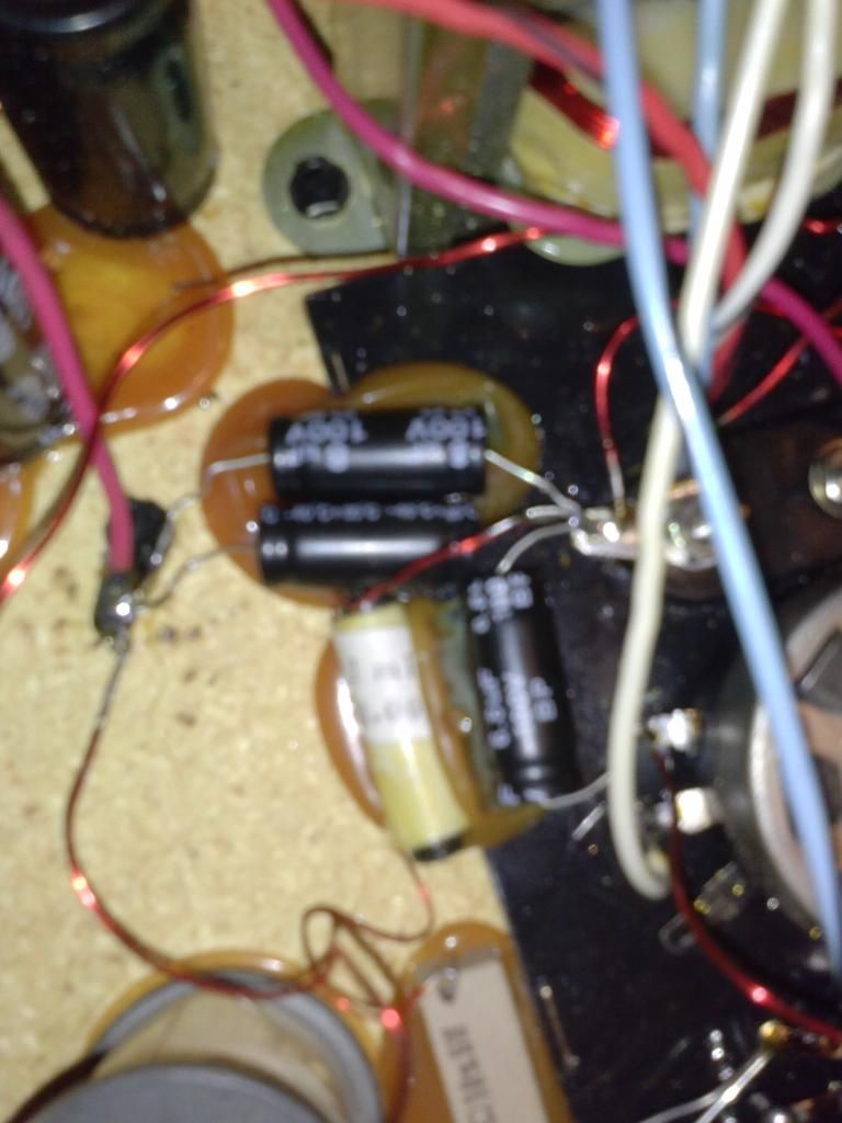
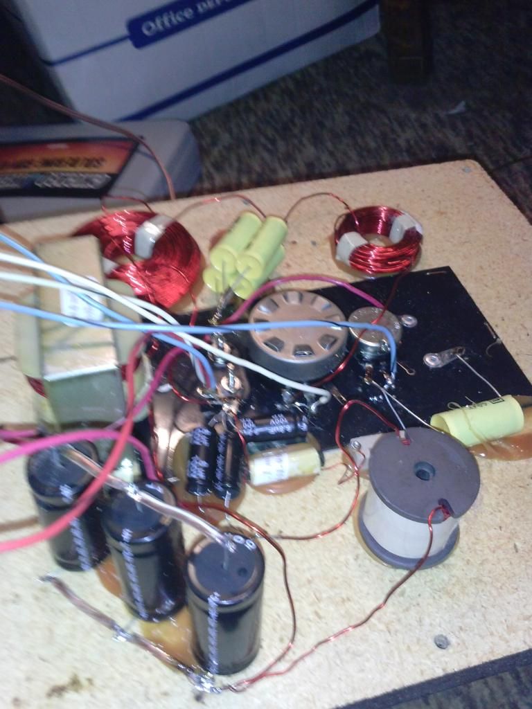
Here are some pics, I'm kind of embarrassed to show them because I know my soldering skills are terrible. The first four are from the speaker I haven't messed with yet and the last are from what I did.
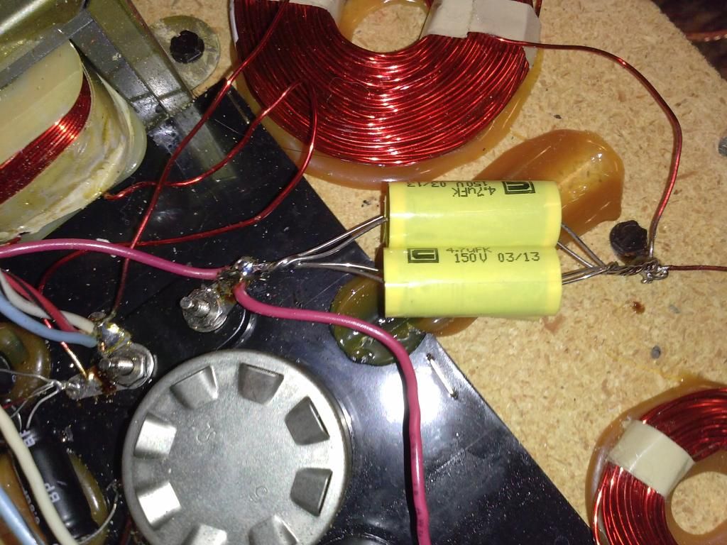
And these are the ones I put in.
I think my 400uf's were around 430, I checked them all. The 600uf's I pulled out were around 700uf, go figure.
It's hard to explain, but it seems like the bass volume/intensity is way down and the lower mid-range is weak. When I turn it up bass/lows aren't crisp or sharp.
The emits/tweeter is amazing though, like crystal
Here are some pics, I'm kind of embarrassed to show them because I know my soldering skills are terrible. The first four are from the speaker I haven't messed with yet and the last are from what I did.
And these are the ones I put in.
Last edited:
toxcrusadr
Omelette au Fromage
Possibilities to consider:
1. Did you replace one part at a time to make it easier to get the connections correct? Countless people have made mistakes by cutting out all the old stuff first, losing track of what's what.
2. Looks like you used nonpolar electrolytics (NPE's) for lower values (5-10 uf), might have been better to use film caps here. The NPE's are cheaper and quite a bit smaller so they work well in high cap value situations, but personally I don't use them for anything below 10-15 uf. That lower range is mids and tweets, so your choice of caps may have something to do with the sound.
3. If you reconnected drivers wrong - out of phase from the original design - there will be humps and dips in the overall response curve.
4. If any of the above are not consistent between the two speakers, additional sonic carnage will result. Particularly woofers being in phase between the two speakers.
Check 1, 2 and 4 first and if they don't sound good, consider spending a couple bucks on better caps for the mid and tweet circuits. JMHO.
[Edit: to add to #2, looks like from the schematic there's a 19 uf cap in series with the midrange, that's another place to use a good quality cap.]
Seppo
Super Member
Regarding loss of bass on the dual woofers, note that both woofers have to be in-series, and in-phase (i.e. positive of one woofer hooked up to the negative of the other woofer) with respect to each other. If you have them out-of-phase (i.e. opposite polarity to be exact), your bass response will be pretty much non-existent.
I had to deal with the above first hand, as one of the woofer pairs in my IIIa's were wired correctly, while the other speaker/woofer pair was incorrect when I bought them.
I had to deal with the above first hand, as one of the woofer pairs in my IIIa's were wired correctly, while the other speaker/woofer pair was incorrect when I bought them.
Bkphoto
Super Member
Woofers...yeah start there first.. + from the crossover goes to the + of the bottom woofer... - from bottom goes to + on top woofer then - goes back to the crossover..
you did the bass side elects the hard way, its easier just to wrap all of them around a common lead...
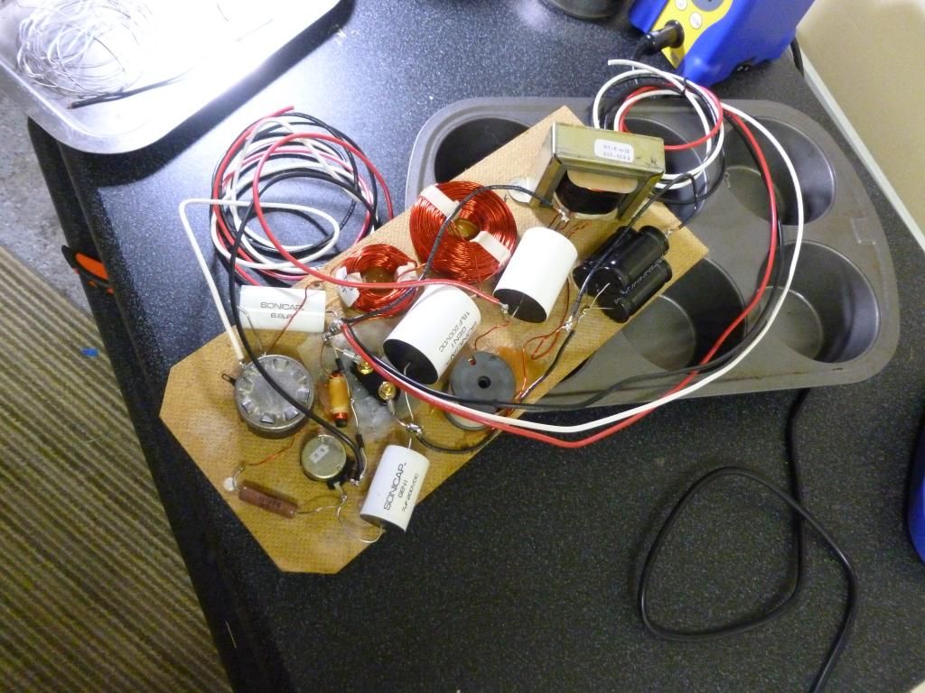
stack them like logs...
you did the bass side elects the hard way, its easier just to wrap all of them around a common lead...

stack them like logs...
Last edited:
Here is what mine looked like at the end...Amoung other things I also replaced the input spring clips with heavy duty binding posts... I did away with the protection on the mids and tweets...
Bk, I took a look at your other pictures and you did an awesome job on the refinishing. What did you use for the initial stripping of the old finish. Mine need refinished and I have all the drivers out already, refoaming the woofers right now, and want to recap them, but would like to refinish them first. I also want to make a set of grills for them out of 1/2" MDF. They didn't have grills when I bought them. I'm looking for dimensions for those, but I'll work on that after they're refinished. Any advice on the stripping and refinishing would be mush appreciated.
Thanks, Chris
Infidel
New Member
Based on the glue, I would say these are original parts in a RS-IIIb / RSIIIb .
This would be a very late model, the blue caps have a date code indicating they were manufactured on the 45th week of 1986.
Those of you that did these mod's a few years ago, how do you like the sound now that the capacitors are definitely burned in?
I'm trying to replace at the very least the 600uf 100v bipolar capacitor, or whatever combination in parallel gets me there.
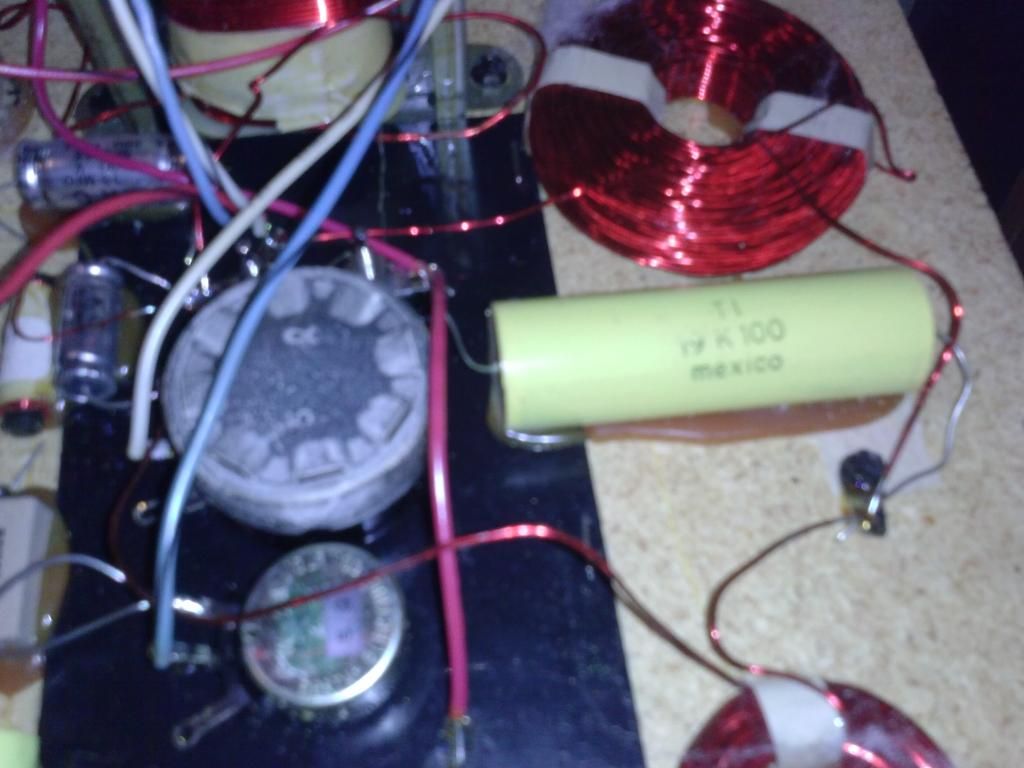
That capacitor listed on the IIIb diagram on page 1 of this thread - any known spec's on it? It is the brighter yellow one in the center, 250V DC, 16.5 MF.
Blue electrolytic caps are from Richey.
Any known voltage rating for the PP cap for the tweeter?
I will most likely have to work in the cabinet, only access is by removing a woofer. Thanks to the picture I can see there is a different adhesive in addition to the screws holding the crossover to the back of the cabinet.
This would be a very late model, the blue caps have a date code indicating they were manufactured on the 45th week of 1986.
Those of you that did these mod's a few years ago, how do you like the sound now that the capacitors are definitely burned in?
I'm trying to replace at the very least the 600uf 100v bipolar capacitor, or whatever combination in parallel gets me there.
That capacitor listed on the IIIb diagram on page 1 of this thread - any known spec's on it? It is the brighter yellow one in the center, 250V DC, 16.5 MF.
Blue electrolytic caps are from Richey.
Any known voltage rating for the PP cap for the tweeter?
I will most likely have to work in the cabinet, only access is by removing a woofer. Thanks to the picture I can see there is a different adhesive in addition to the screws holding the crossover to the back of the cabinet.
toxcrusadr
Omelette au Fromage
"That capacitor listed on the IIIb diagram on page 1 of this thread - any known spec's on it? It is the brighter yellow one in the center, 250V DC, 16.5 MF."
What other specs would there be?
What other specs would there be?
Infidel
New Member
What other specs?
polar or bipolar
I'm not thinking it is aluminum electrolytic but maybe polypropylene or maybe the abbreviation of "MM" means something in 1980's capacitor terminology.
maybe if it were known (based on function) to be a flabby and slow cap or a fast cap.
Things like that...
Where I would normally see a hint at a manufacturers name there is KSC.
Based on its shape and size, it looks like it could hold two separate cap's, perhaps wrapped side by side and in parallel to get the unusual 16.5uF
Similar threads
- Replies
- 10
- Views
- 1K
- Replies
- 8
- Views
- 1K