....
I've priced out the electrolytics for the power supply board with Panasonics from both Mouser and Digikey about the same price.
Both are excellent and are the first places most here go to for parts. I suggest trying them both. If funding is very tight DK has a free shipping option if an order is prepaid by check or MO. I believe Mouser has a better selection of transistors. If Mouser doesn't have a certain transistor then B&D might be next up in your search.
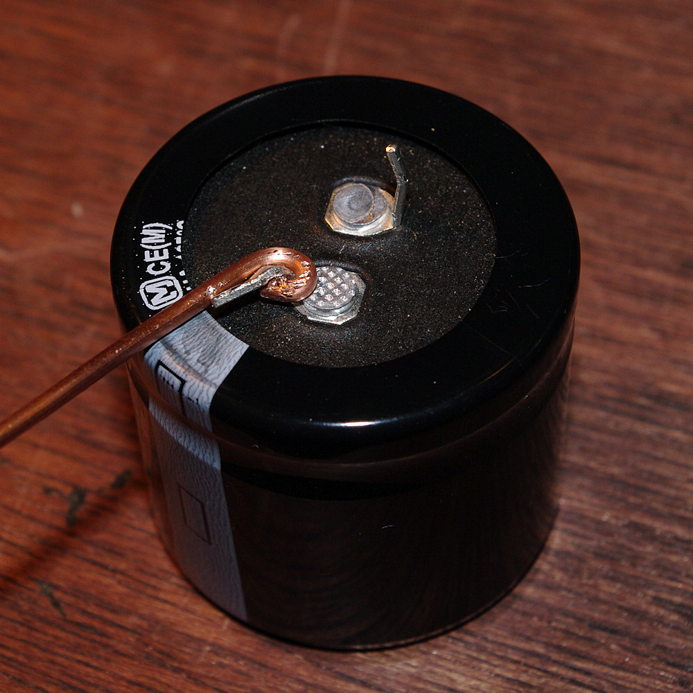
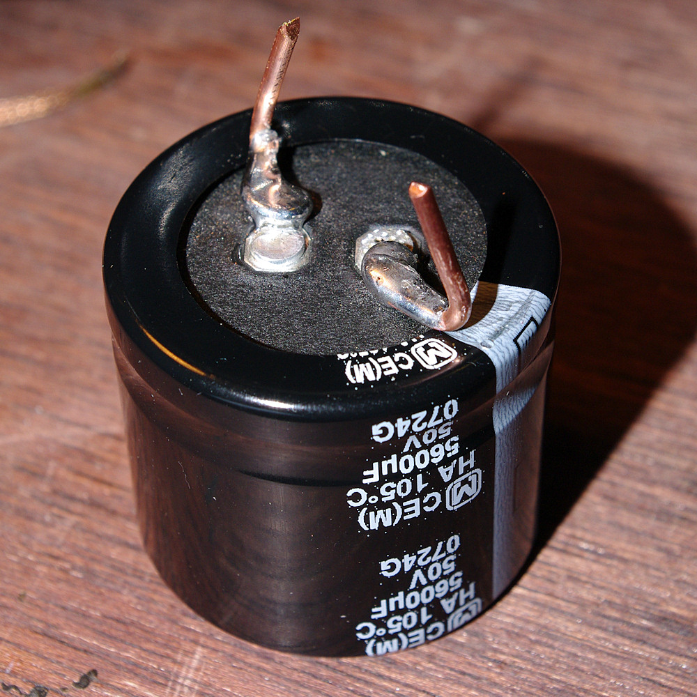
The 2 I'm having trouble finding are the 15000uf 63v that sit next to the transformer in the center of the chasis. The 2 connection 'lugs' on the bottom are larger than anything I've found online. I should have taken a picture while I had the bottom off - maybe it doesn't matter?
This is another of the common hurdles in recapping. I suggest taking one of them out, measuring, posting pics here, searching various sellers, etc. I am going to respectfully disagree with the previous post. I could be wrong but I believe that 10mm is standard lead spacing for snap-in type caps, but there are other types out there. You may find a closer match or something easier to work with, with a wider spacing, in a different type of cap.
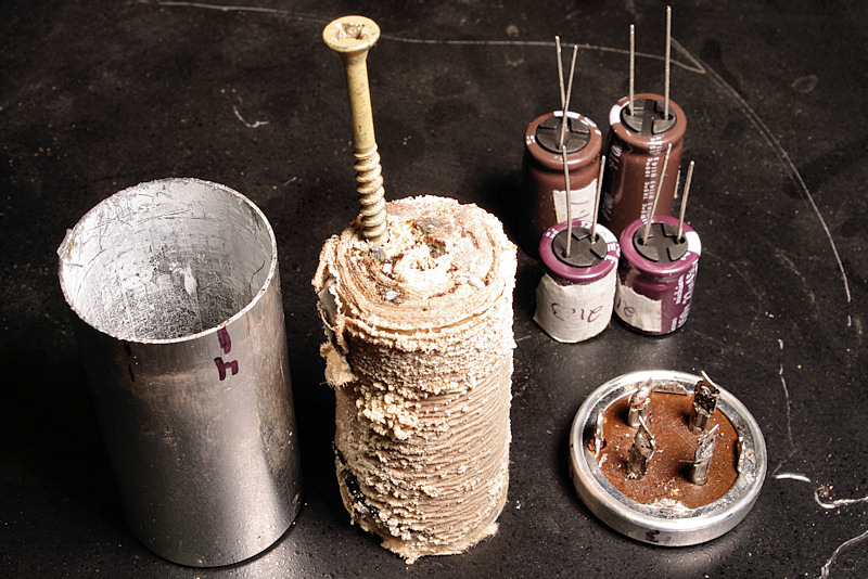
Sometimes a bit of improvising is required, sometimes not. My KA-4006 filter caps were replaced with computer type screw lug caps. Very neat and easy (also shown in my thread linked below). Also, you might search (AK advanced search and/or google search of AK) for threads on the KA-8006. I believe that pete_mac did one of these. I don't know whether he addressed this topic in his thread. But someone else may have.
Regardless, I thought I would start with the Power Supply board, should I expect to hear any improvement, or does that come only after doing main amp, filter, and tone boards?
IMO you should be able to notice improvement by doing only the power supply board. In fact, it is a very good idea to do the work in small chunks and then test for problems before proceeding further.
I have yet to see how the pre-amp performs on it's own. I've got a Pioneer SX-1000TW that sounds great, so I think I will take the KA-8006 pre-out to an Aux in on the SX-1000TW and see how it compares. That should give me an idea if I need to do anything with the pre-amp board on the Kenwood, yes?
Two things here:
1) Does KA-8006 have pre-out and amp-in connections? I ask because my KA-4006 does not, but it has something similar looking that is actually made for interfacing with a 4-channel set-up that existed back then. The link below is to the post in my thread about the 4-channel interface and its functionality.
http://www.audiokarma.org/forums/showpost.php?p=6217533&postcount=109
2) If your amp has real pre/main jacks then by all means test out each section separately before doing any work. As a general suggestion, observing everything you can before making changes is a good idea. Sometimes I have made a change and afterwards became aware of something that I had not noticed previously...then I am not sure whether the thing I am noticing was there before or whether I caused it.
Yes, it does
")
OK, one last thing specific to the KA-4006 and I would assume also your amp. The wires wrapped around the posts are solid, small, and fragile. Repeated bending can cause these wires to break, usually near the base of the post where the wire emerges from its winding. Efficiency in limiting the number of times any board with these wires connected needs to be turned over and back, as well as a gentle hand, is time and effort saved.