Epic Fail with Sparks Setting Bias on SX-9000

JamVal

Addicted Member
I was checking and setting bias on a SX-9000 - according to a procedure I found on another thread here.

To make a long story short I taped wire leads to the R31 and R32 solder joints on the PC board to facilitate use of mini-grabbers. For some reason the lead on that side of the resistor is insulated.

The following layout shows where I connected a wire lead (green line) for the black lead of the DMM, and just attached the DMM red grabber to the other side of the resistor which isn't insulated.

W23_010Layout_zpsxntl6tt8.jpg


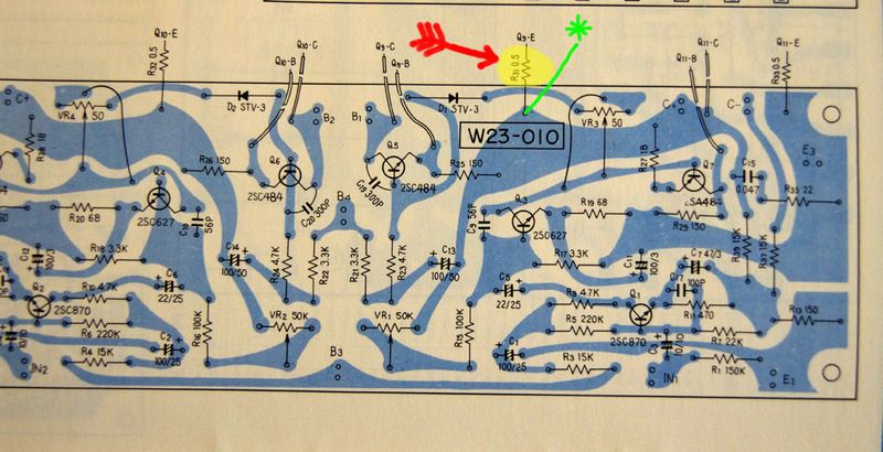
This was all going well. Checking for 15mv. Left side was reading high - 40mv. So I adjusted to about 16mv - close as I could get using trim pot Vr3.

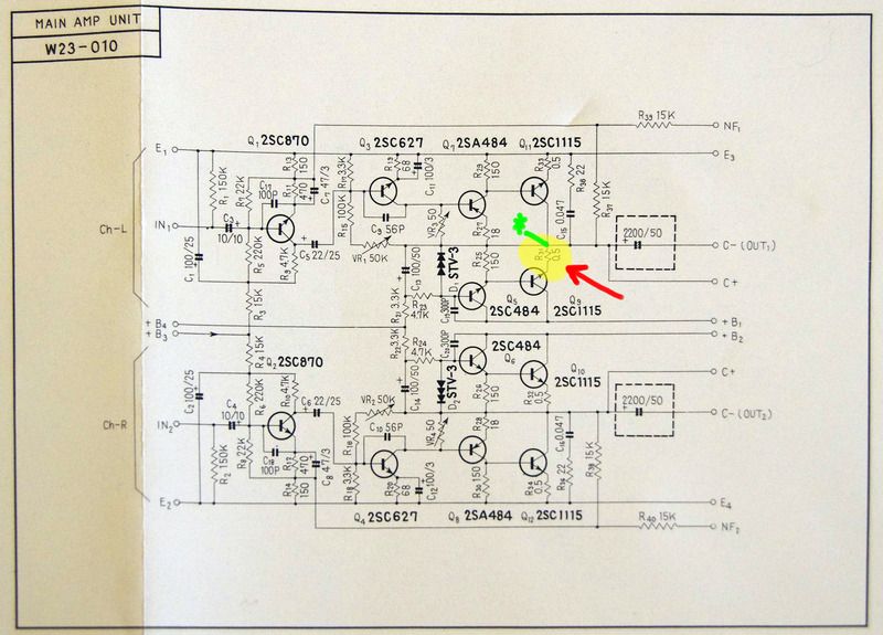
As I disconnected the black mini-grabber from my make shift wire lead, the wire sprung away and touched the chassis and a spark flew. Now I get a constant reading of 4.0mv across the R31 resistor for the left channel, adjusting Vr3 for the left channel does nothing - 4.0mv no matter where I set Vr3. So I fried something - but what?

Here is a schematic of the main amp board with the R31 resistor highlighted in yellow and showing a green line where I attached the lead that sparked to the chassis.

W23_010Schematic_zpsy3vjayhe.jpg


I could kick myself. Tried to be so careful. Exercised and cleaned the trim pots without power, then powered it up on a dim bulb tester to make sure before tinkering. One slip and POP!
 
Thanks again for your help Pete. If you haven't noticed, I'm a complete newb to all this. So, when you say check the voltages at the outputs, I assume you mean the TO-3 style transistors on the heat sink which that R31 resistor is connected to? Anyhow, I checked voltage on those (2sc1115). From what I can tell the resistor is connected to the Emitter pin. I'm not sure if the other pin is the Collector or the Base, but I checked voltage across the transistor pins:

Q9 on the left channel = 0.000v
Q10 on the right channel = .590v

Q11 on the left channel = .513v
Q12 on the right channel = .577v

Q9 with no voltage, is connected to that R31 resistor that I shorted out against the chassis - so does this mean I destroyed that transistor?

I didn't check r25 and r29 for 150 ohms, do I need to pull them from the circuit to do that?
 
you need to get voltage readings with one meter to chassis ground the black one .the other to each pin and the case ..the transistor case is the collector .
check the resistors in circuit for now with the power off .
 
Sorry again for not knowing what I'm doing.

Here are the readings.

Left Channel Q9 E = 20.1v, B = 20.1v, C(case) = 20.1v
Left Channel Q11 E = 0.0v, B = 0.4v, C(Case) = 20.1v

Right Channel Q10 E = 38.4v, B = 38.9v, C(case) = 88.5v
Right Channel Q12 E = 0.0v, B = 0.5v, C(case) = 38.3v

R25 = 125 ohm (readings bouncing, hard to get a good one, had to take these from the bottom solder joint side of the board, this board is buried under another board.
R29 = 150 ohm
 
q9 appears dead . needs pulling out to verify with your meter on diode test .
actually its best to pull and test q5 q6 q9 and q11 .
looks like there is more damage too . the 3 amp fuse for +b1 or a burned trace on the board .
it is possible that the fuse is blown and q5 and q9 are shorted .
 
by the way DON'T replace the fuse yet thinking it will fix the issue ..unless you like firework shows .
 
q9 appears dead . needs pulling out to verify with your meter on diode test .
actually its best to pull and test q5 q6 q9 and q11 .
looks like there is more damage too . the 3 amp fuse for +b1 or a burned trace on the board .
it is possible that the fuse is blown and q5 and q9 are shorted .

Yes, the fuse for that channel is blown, the filament is broken.

One question, did you mean Q7 instead of Q6? Q6 is on the right channel, while Q5, Q7, Q9, Q11 are on the left. Fortunately it looks like I can just reach Q5, Q7. The rest of that board is buried.

I'm not sure it's worth fixing, certainly not if I have to pay a tech to do it. This unit didn't sound that great to me when I started (sounds like sour grapes now that I messed it up real good)
 
That's the same amp as in the sx-770. Don't worry in the end the set will be better and more reliable. I have the recipe! Very good amp to learn on.
Curious, Why where you messing with it? Any issues you forgot to mention?
Just watching.
 
Last edited:
yes i meant q7 .. all transistors are odd numbers in the left "blown" channel .
if you feel put off right now as am thinking you will be as i would . put it to one side and pick it up later . you can test for shorted transistors in circuit but they need pulling out to be sure .
 
That's the same amp as in the sx-770. Don't worry in the end the set will be better and more reliable. I have the recipe! Very good amp to learn on.
Curious, Why where you messing with it? Any issues you forgot to mention?
Just watching.

Thanks for watching.
Wish I hadn't messed with it now. One thing lead to another.
I got it last year. After cleaning it all up it just never sounded that good to me. Weak volume, and seems to distort at too low a volume.

It also has an audible hiss from each channel on all inputs including tape monitor. The hiss doesn't seem to be volume dependent, it's just there all the time. It's not real loud, just enough to be annoying.

So I did a search here on the SX-9000 and found a discussion on checking center point voltage and bias. I read that voltage across resistor R31/R32 (L/R) connected to the emitter side of outputs Q9/Q11 should be 15mv. So I pulled the cover and found it to be around 40mv and 25mv (L/R). I thought, what the heck, the trim pots are right there why not adjust it while I'm in there. POP!

And thanks for the offer to fix it. I'm just getting into this hobby, so I think I may give it a shot myself. I'm sure I will have many more questions.
Thanks again.
 
It's old and has life limited parts in it. A perfect set to start into this hobby. The 770 I just restored sounds fantastic. Like Pete said. step back and regroup. Let us know when you're ready.
 
yes i meant q7 .. all transistors are odd numbers in the left "blown" channel .
if you feel put off right now as am thinking you will be as i would . put it to one side and pick it up later . you can test for shorted transistors in circuit but they need pulling out to be sure .

I slept on it, and have a probable dumb question.
How do I check for shorted transistors in circuit? since the fuse for the bad side is blown, will that effect it?

If I power up the SX-9000 with a good fuse on a dim bulb tester, will that tell me anything? Again, I don't know what I'm doing, but my understanding was that if the bulb burns bright after power up on a DBT it means there is a short somewhere. But if the bulb goes dim on power up, could it still mean that there are problems?
 
those voltage reading are telling me one or more transistors are shorted .
to test for shorts remove the power first .unplug the unit from the wall .
having it powered up is asking for trouble until its fixed .
test between transistor pins on ohms . transistors when shorted are generally from collector to emitter .but can be shorted any which way between junctions .

Thanks Pete. So I can take readings from the good ones on the right channel and compare to those on the left.

Going onto the board for Q5 & Q7 may be a bit more of a challenge than the outputs. They are partially obscured by a board above them, but I can get to the under side from the bottom and check them at the solder joints, the layout in the service manual will help me with the pinouts E,B,C . Maybe this will be the opportunity to finally get NPN, PNP pinout orientation straight in my mind. ".. in all things God works for the good...." Rom 8:28 :yes:

I'm probably getting ahead of myself, but if I have to go with substitutes, should I also replace the right channel outputs with the same substitutes?
I recall reading somewhere that the main amp transistors should be 'matched', but I don't recall if that was referring to the 'input pair' or output pair or both.

Thanks again, without you folks here I would be lost. :thmbsp:
 
Watching this thread intently. Recently picked one of these up too and was going to start doing some updating as well.

Lots of boards and caps on these. Mine is noisy too but it still sounds sweet.

How was your reverb board before it was out of commission?
 
How was your reverb board before it was out of commission?

As I recall when I first got this last summer the reverb didn't seem to do anything. After giving all the pots and switches a good cleaning it worked. But it's not something I would use, I didn't like the sound of it.

The guy I got it from was the original owner. He told me that he never liked or used the reverb either. He was telling me that it was a primitive attempt to do something like the Carver Sonic Halography - whatever that is. He said you had to have the speakers and your listening location just right to get the best effect from it.

I got it bundled with a set of CS-99 speakers an Akai reel-to-reel, a Garrard Turntable, Pioneer Headphones, Tapes, Mics, etc. The owner bought it all new from an Navy Exchange store in Asia around 1970. It even came with the "US Military Only" warranty cards. He must of had some money set aside - that was a TOTL system then. Even with the big discounts in the military exchange system, it was still a chunk of cash.

I was in the military at the same time, stationed in Asia, but for some reason I could never save enough money for any system. My money went to wine & women, but ran out when it came to the song part. :D
 
Back
Top Bottom